반드시 알아야 할 "DC/DC 컨버터" 전원설계 기초
기사입력 2020.10.26 15:20
고효율, 소형화 추구하는 최근의 전자제품
컨버터 선택 시 장점 및 효율 고려 필요
출력 형식 따라 LDO와 DC/DC로 구분
콘센트가 연결되어 동작하는 대부분의 전자제품은 AC(교류) 220V를 DC(직류)로 변환하는 'AC/DC 컨버터'가 필요하다. 반도체 부품 다수가 DC로 동작하기 때문이다. 또한, 세트 기판의 IC는 각각 동작 전압 범위가 다르며, 전압 요구도 다르다.
따라서 전압이 불안정한 전원을 공급하면 오동작 또는 특성 열화 등의 문제를 초래한다. 따라서 필요한 전압으로 변환하거나 안정화하기 위한 'DC/DC 컨버터'가 필요하다. 이번 기사를 통해 DC/DC 컨버터 전원설계 기초와 레귤레이터 동작 원리에 대해 알아보자.
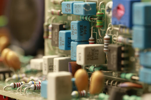
▲ DC/DC 컨버터는 회로에 안정적인 전압을 공급하기 위해 사용된다
전원 IC의 종류
전원 IC의 종류에는 리니어 타입의 'LDO'와 스위칭 타입의 'DC/DC 컨버터' 두 종류가 있다.
출력 형식에서 LDO는 입력전압보다 낮은 전압을 만드는 △강압 1가지지만, DC/DC 컨버터는 △강압, △승압, △승강압, △반전 등 4가지로 다양하다. 정류방식 또한 DC/DC 컨버터에만 △동기 정류, △다이오드 정류 두 가지가 있다.
LDO vs DC/DC 컨버터
LDO는 노이즈가 적고 회로가 간단한게 장점이다. 반면 입출력 전압차에 따라 소비전력이 함께 커져 발열이 심해 효율이 낮아진다. 또한, 입력보다 낮은 전압만 생성할 수 있다.
DC/DC 컨버터는 입출력 전압 차가 커도 고효율로 대전류에 대응할 수 있다. 또한, 전압 출력 형식이 자유로운 장점이 있다. 하지만 외장부품이 많아 회로가 복잡하고 설계할 때 스위칭 시 발생할 노이즈를 고려해야 한다.
LDO의 동작 원리
LDO는 에러 앰프, 귀환, 출력 트렌지스터로 구성되어 있다. 부하전류가 변화하여 변동되면 에러 앰프가 출력 트렌지스터를 제어해 출력 전압은 항상 일정하게 되도록 움직인다.
이 회로는 관전 증폭회로와 같으며 귀환 루프에 출력 트렌지스터가 들어있다. 에러엠프의 비반전 단자 전압은 VREF와 동일하게 되도록 제어되기 때문에 전류는 항상 일정하게 유지된다. 따라서 전류는 VREF/R2일 때, VO=R1+R2/R2*VREF이다.
DC/DC 컨버터의 동작 원리
일반적인 DC/DC 컨버터 기본 회로에는 S1, S2 모스펫 다이오드가 사용되며, 동작 원리는 다음과 같다.
1. 비교 회로에서 출력 전압이 설정 전압으로 되어 있는지 기준 전압과 비교한다.
2. 기존 전압보다 설정 전압이 낮으면 스위치가 켜져 입력에서 출력으로 전력을 공급한다.
3. 이때 전류가 흐르며 인덕터에 자기 에너지를 축적한다.
4. 전력이 공급되고 출력 전압이 설정 전압보다 높아지면 스위치는 꺼진다.
5. 이때 전류는 녹색 경로로 흘러 인덕터에 축적되어있던 자기 에너지가 전류가 되어 부하출력에 공급되며 다이오드를 통해 다시 인덕터로 돌아온다.
6. 인덕터에 자기 에너지가 낮아져 기존 전압보다 설정 전압이 낮아지면 스위치가 다시 켜진다.
7. 이를 스위칭 주파수로 반복한다.
이처럼 DC/DC 컨버터는 필요한 전력만 입력에서 공급받아 고효율이 되지만 출력 전압에 리플전압이 개입한다.
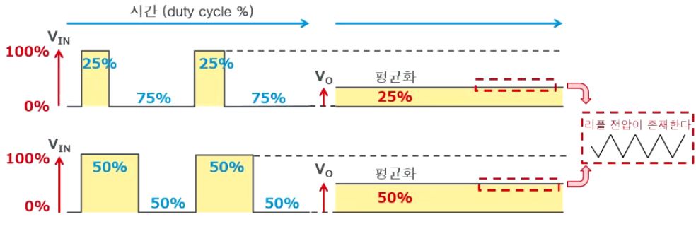
▲ DC/DC 컨버터는 출력전압에 리플전압이라는
전압의 흔들림이 발생한다 [제공=로옴]
전압의 흔들림이 발생한다 [제공=로옴]
정류 방식에 따른 비교
비동기 정류방식과 동기 정류방식은 등가회로 하측 스위치로 사용되는 소자가 다이오드인지 MOSFET인지에 따라 구분한다.
동기정류(MOSFET 정류) 타입의 불연속 동작
다이오드는 경부하에서 고효율 관통이 없다는 장점이 있지만, 중부하에서 효율이 낮고 경부하에서 불연속으로 동작한다. 동기정류는 중부하에서 고효율, 고속응답을 한다. 하지만 회로가 다소 복잡하고 경부하에서 효율이 낮다. 따라서 FET 외장의 경우 관통 전류에 대한 대책이 필요하다.
모든 회로는 전류가 스위치를 통해 흐르기 때문에 스위치에 손실로 효율에 영향을 미친다. 따라서 정류방식에 손실차가 생기게 된다. 손실은 다이오드의 경우 순방향 전압 VF트렌지스터의 경우 포화 전압이나 온저항이 된다.
다이오드의 VF는 전류에 의해 바뀌지만, VF가 낮은 쇼트 키 다이오드도 0.4~0.7V가 있다. 반면 MOSFET의 RON은 수십mΩ~수백mΩ으로 매우 낮다. 전압강하를 예상하면 다이오드VF보다 훨씬 낮아진다.
비동기정류(다이오드 정류) 타입의 불연속 동작
다이오드 정류 타임의 DC/DC 컨버터에는 연속 동작과 불연속 동작이 존재한다. 인덕터에 흐르는 전류가 지속적인 연속 동작인 반면, 불연속 동작은 인덕터에 흐르는 전류가 단속적(0이 되는 구간)인 동작을 나타낸다.
고효율, 소형화 요구에 따라 DC/DC컨버터 존재감이 높아지고 있다. 따라서 컨버터를 선택할 때 아날로그 회로 설계에 각 장점과 효율을 생각해서 설계해야 한다. 더 자세한 DC/DC 컨버터 전원설계 및 동작원리는 e4ds EE웨비나의 '로움 Web 세미나 [30분 만에 끝내는 DC/DC 컨버터 입문]'에서 확인할 수 있다.
김동우 기자
관련뉴스
-
ADI, DC/DC 컨버터 통합한 전력 송수신기 신제품 출시
아나로그디바이스가 iCoupler 절연형 RS485와 절연형 DC/DC 컨버터를 통합한 ADM2867E 전력 송수신기를 출시했다. ADM2867E는 방사 방출이 적을 뿐 아니라 적은 산으로 EMC 적합성을 충족할 수 있게 한다. IEC 61000-4-2 ESD 보호 기능을 지원하여 열악한 환경에서도 신호 무결성을 유지한다.
2020-06-03 오전 8:40:55by 이수민 기자
-

[인터뷰] "DC/DC 컨버터, 주변 회로 설계가 중요하다"
콘센트 전원으로 동작하는 전자제품은 AC 220V를 DC로 변환하는 AC/DC 컨버터가 필요하다. 대부분의 IC가 DC로만 동작하기 때문이다. DC/DC 컨버터 또한 중요하다. 전자제품에 사용되는 수많은 IC는 저마다 동작 전압, 전압 정밀도 요구가 다른데, 전압이 불안정한 전원은 IC의 오동작과 특성 열화 등의 문제를 일으키기 때문이다.
2020-08-21 오후 3:11:22by 이수민 기자
-

TI, 스마트 계량기용 DC/DC 벅 부스트 컨버터 공개
스마트 계량기에 적합한 TI의 TPS63900 DC/DC 벅 부스트 컨버터는 대기 전류가 75nA 정도로 낮으며, 1.8~5V 범위 내에서 출력 전압을 프로그래밍할 수 있다. 또한, 동적 전압 스케일링 기능을 사용하면 애플리케이션이 작동하는 중에 출력 전압을 전환할 수 있다.
2020-09-02 오후 4:01:32by 강정규 기자


.jpg)

많이 본 뉴스
[열린보도원칙] 당 매체는 독자와 취재원 등 뉴스이용자의 권리 보장을 위해 반론이나 정정보도, 추후보도를 요청할 수 있는 창구를 열어두고 있음을 알려드립니다.
고충처리인 장은성 070-4699-5321 , news@e4ds.com