[웨비나리뷰]인피니언, “BMS MOSFET 병렬 사용시 VGS(th) 주의 必”
기사입력 2023.05.12 16:43
▲김용진 인피니언 이사
애플리케이션 따른 BMS 구성 차이 설명
MOSFET 병렬 사용 시 중요 파라미터 소개
인피니언이 빠르게 성장하는 배터리 구동 애플리케이션 시장에서 배터리의 충전 및 방전을 모니터링하고 조절하는 전자 제어 회로인 배터리 관리 시스템(이하 BMS)의 중요성에 대해 강조하며 BMS의 구성요소와 인피니언의 솔루션을 소개했다.
김용진 인피니언 이사는 지난 9일 e4ds news 웨비나에서 ‘배터리 관리 시스템의 구성 요소 및 보호용 MOSFET선정 기준에 대한 이해’를 주제로 웨비나를 진행하며 △BMS의 기본 구성 요소 및 동작 설명 △보호 스위치로서의 MOSFET 선정 시 주의 사항 △BMS에 대한 인피니언 솔루션에 대한 내용을 발표했다.
BMS는 리튬이온 배터리를 보호하고, 배터리에 남아있는 용량을 예측하여 표시하는 SOC(State of Charge), 배터리 수명을 예측하는 SOH(State of Health), 여러 배터리가 직렬로 연결되어 있을 때 각 배터리 셀의 밸런싱을 하거나, 정품 배터리인지 확인하는 등을 가지고 있다.
BMS는 스마트 스피커, 노트북 등 소형 전자기기에서 무선 청소기, 드론, 로봇 등의 소형 모터 기반 애플리케이션, e-바이크와 같은 대형 모터 기반의 애플리케이션, 서버, ESS와 같은 산업용 대형 애플리케이션에 다양하게 적용되고 있다.
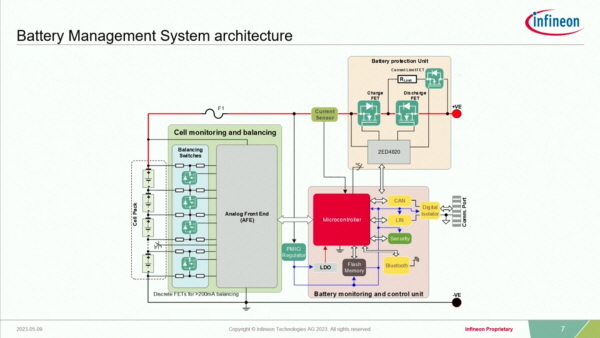
BMS의 구성요소는 △MOSFET 등을 위치해 배터리를 보호하는 배터리 프로텍션 유닛 △각 셀의 전압을 모니터링하고 충전하는 데 밸런싱을 맞춰주는 셀 모니터링&밸런싱(CMB) △외부와 커뮤니케이션하는 배터리 모니터링&컨트롤 유닛 △배터리의 충전/방전 전류를 센싱하는 Current Sensor △각각의 유닛에 전원을 공급하는 PMIC 혹은 레귤레이터로 구성되어 있다.
배터리 프로텍션 기능은 배터리가 과충전/방전되지 않도록 배터리 셀을 보호하며 외부로부터의 Inrush Current를 막을 수 있으며, 충방전 시 발생하는 열을 효율적으로 관리한다.
CMB는 셀의 전압, 충방전 시 온도, 직렬로 연결되어 있는 배터리팩의 전체 전압 등을 모니터링 한다.
애플리케이션에 따라 BMS 구성에 차이가 있다.
파워뱅크, 휴대용 기기와 같은 애플리케이션은 직렬로 연결된 배터리로부터 전압을 내려 USB를 통해 전원을 공급하거나, 반대로 USB에서 전압을 올려 직렬 배터리로 전원을 공급할 수 있도록 벅 부스트 회로가 추가된다.
싱글 배터리팩을 직렬로 쌓아 멀티 모듈 형태로 사용되는 산업용 ESS와 같은 애플리케이션에서는 적게는 수 백 볼트, 높게는 수 천 볼트의 전압이 형성된다.
안전성 확보를 위해 각 배터리 모듈 간에 절연을 할 필요가 있으며, 절연 상태에서의 각 모듈 간 통신이 이루어져야 한다. 또한, 프로텍션 스위치로 MOSFET이 아닌 Relay가 사용된다.
배터리 보호용 스위치로 MOSFET을 사용할 경우의 구성 방법을 설명했다.
프로텍션 서킷 유닛은 배터리의 각 +, - 단자 가까이 위치시킬 수 있다.
+ 단자 가까이 위치시켰을 때는 그라운드 레벨이 동일해 통신 등을 컨트롤하는 데 있어 offset을 고려할 필요가 없다. 다만, 프로텍션 서킷에 사용되는 MOSFET은 N-Channel MOSFET을 사용하는데 이는 소스 터미널 대비 게이트 터미널이 항상 높은 전압을 가져야 하기 때문에 차지 펌프 기능을 가진 게이트 드라이버를 사용해야 한다는 단점이 있다.
프로텍션 서킷을 – 단자 가까이 위치시키면 차지 펌프는 필요 없으나 프로텍션 서킷 좌우로 레벨이 달라지는 부분이 있어 외부와 BMS 모듈 간 통신을 위해 별도의 Isolation 등으로 커뮤니케이션 해야 한다.
배터리 프로텍션 스위치 MOSFET 연결법에 대해서 설명하며 백투백 형태인 Common Source와 Common Drain을 소개했다.
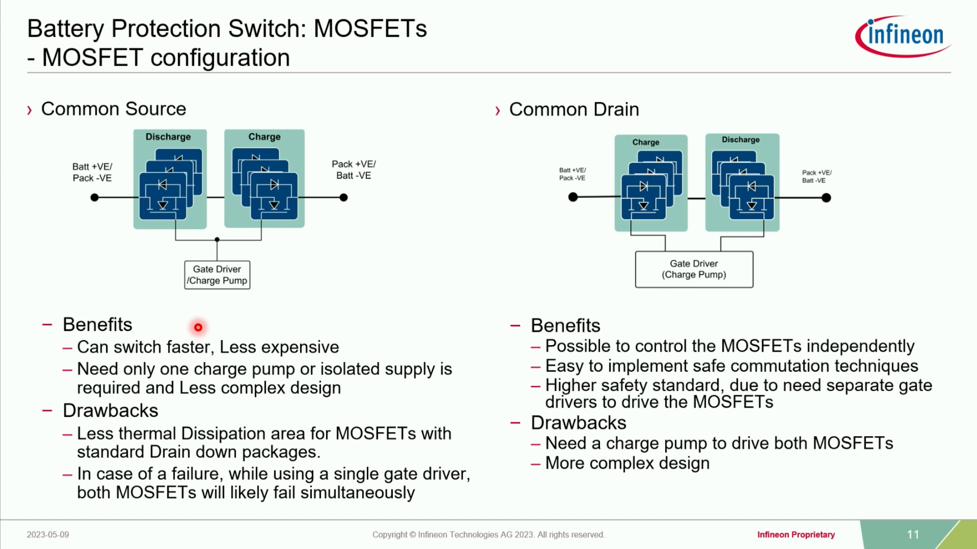
Common Source의 장점은 두 개의 스위치가 하나의 게이트 시그널로 Turn on/off가 되기 때문에 스위치 동작이 빠르고 비교적 저렴하다. 반면, 하나의 스위치에 문제가 생겼을 때 전체 MOSFET에 영향을 끼친다.
Common Drain은 게이트 드라이버가 각각의 MOSFET을 구동하기 위해 시그널이 두 개다. 때문에 이는 하나의 게이트 드라이버에 두 개의 차지 펌프 기능이 있어야 한다. 각 MOSFET을 별도로 구동할 수 있어 안정성이 뛰어나다.
김용진 이사는 MOSFET을 병렬로 사용할 때 가장 고려해야 할 파라미터는 VGS(th)라고 전했다.
VGS(th)가 차이가 커질수록 각 MOSFET에 흐르는 파워 로스가 커진다. VGS(th)가 1.6V 차이가 날 때는 0V일 때보다 88% 증가하는 모습을 보였다.
MOSFET을 6개를 병렬로 연결 시 완전히 Turn on 되었을 때 Conduction Loss는 큰 차이가 없으나, Turn on/off 되는 순간에는 VGS(th) 편차가 클수록 Loss가 크다.
인피니언의 MOSFET은 VGS(th)의 최소, 최대 차이가 경쟁사 대비 더 적어 다수의 MOSFET을 병렬로 사용하는 애플리케이션에서 유리하다고 설명했다.
이어 김 이사는 인피니언의 BMS 솔루션을 소개하며 “BMS는 MOSFET을 병렬로 사용하는 경우가 많다”며 “고객들은 MOSFET을 병렬로 사용할 때 사이즈가 점점 커지는 문제를 해결하기 위한 고민을 많이 한다”고 전했다.
이러한 문제로 인해 고객들은 작은 패키지의 더 작은 RDS(on)의 제품을 요구한다.
인피니언은 StrongIRFET과 OptiMOS 두 가지 제품군을 가지고 있다.
김 이사는 BMS에는 사이즈를 줄이면서 더 많은 방전 전류에 대해 더 적은 열 상승을 가져가야 하기 때문에 OptiMOS가 적합하다고 설명했다.
.jpg)
가격경쟁력을 추구한다면 전세대 제품을 사용해도 무방하나 병렬 개수가 늘어나야 하는 문제점이 있다고 덧붙였다.
BMS에 사용되는 인피니언의 패키지는 D2PAK, D2PAK 7pin, D2PAK 7pin+가 있다.
패키지 사이즈를 줄이기 위해서는 TO-Leadless(TOLL) 패키지, 탑 사이드에 히트 싱크를 연결해 적은 수의 MOSFET을 사용하더라도 높은 방전 전류를 커버할 수 있는 TOLT 패키지가 있다.
사이즈를 5 x 6으로 낮춘다면, SuperSO8을 프로텍션 MOSFET으로 사용할 수 있고, 전류를 높인 상황에서 병렬 개수를 유지하겠다면 sTOLL 패키지를 사용하면 된다.
노트북과 같은 소형 기기에서는 3.3 x 3.3 패키지를 사용하는 것이 일반적이다.
배터리 프로텍션 스위치로 사용되는 Common Source, Common Drain 형태의 MOSFET은 낮은 RDS(on), 낮은 Thermal Resistance를 가져야 하며, 충분한 Safe operating area, Linear mode에서 강한 내성을 가져야 한다.
김용진 이사는 이어 MOSFET을 구동하기 위한 EiceDRIVER-2ED4820-EM 드라이버, Current Sensor, 셀의 전압 및 밸런싱을 해주는 BMIC에 대해 설명했다.
EiceDRIVER-2ED4820-EM 드라이버는 20~70V를 지원하며 Sleep Mode 시 IC에서 소비되는 전류는 5마이크로암페어보다 더 적다. 내부에 차지펌프가 내장되어 있어 High Side(+ 단자 쪽)에 N-Channel 구동을 할 수 있으며, 두 개의 게이트 시그널이 나오기 때문에 MOSFET의 연결은 Common Drain으로 한다.
인피니언은 20~300V Low, Medium Voltage MOSFET를 보유했고, 600V, 950V 등 높은 Voltage의 실리콘 MOSFET의 제품을 가지고 있다.
XENSIV Magnetic Current Sensor는 △PG-TSON-8 △PG-VSON-6 △PG-TDSO-16 세 가지 형태의 패키지가 있다.
PG-TSON-8은 Current rail이 칩을 통해 지나간다는 특징이 있고, 나머지 두 패키지는 External current rail이다.
XENSIV Magnetic Current Sensor는 두 개의 Over Current Detection 기능을 가지고 있으며, 3.3V로 구동된다.
또한 오토모티브 용도에 맞게 ASIL B에 해당하는 보호 기능을 제공한다.
이외에도 김용진 이사는 TLE9012DQU와 TLE9015DQU IC 제품에 대해서도 소개하며, 인피니언의 다양한 제품군에 대한 정보를 공유했다.
해당 웨비나는 ‘배터리 관리 시스템의 구성 요소 및 보호용 MOSFET선정 기준에 대한 이해’ 링크에서 확인할 수 있다.

배터리 관리 시스템의 구성 요소 및 보호용 MOSFET선정 기준에 대한 이해
2023-05-09 10:30~12:00
Infineon / 김용진 이사


많이 본 뉴스
[열린보도원칙] 당 매체는 독자와 취재원 등 뉴스이용자의 권리 보장을 위해 반론이나 정정보도, 추후보도를 요청할 수 있는 창구를 열어두고 있음을 알려드립니다.
고충처리인 장은성 070-4699-5321 , news@e4ds.com