[기고]나자레노 로제티&조쉬 프랑크하우저 ADI - USB-C PD 데이터 라인을 위한 통합 보호 솔루션
기사입력 2022.08.18 10:28
“통합적 보호 디바이스, ESD·서지·OV 요건 충족”
포괄적 2xSPDT 스위치, 최소면적 BOM·PCB로 보호기능 충족
MAX20334 2xSPDT, 휴대 전자기기 과전압 보호용 사용 적합
포괄적 2xSPDT 스위치, 최소면적 BOM·PCB로 보호기능 충족
MAX20334 2xSPDT, 휴대 전자기기 과전압 보호용 사용 적합
USB-C와 USB-C PD(Power Delivery)는 더 높은 수준의 전압과 전력을 지원한다. 이는 무방향성 커넥터(reversible connector)로서 핀 간격이 USB Micro-B보다 더 촘촘해 단락이 일어날 위험성이 더 높아졌다. 뿐만 아니라 휴대 전자기기들이 갈수록 복잡해짐에 따라 ESD, 서지, 과전압에 대한 보다 향상된 보호가 필요해졌다. 이 글에서는 포괄적인 기능의 컴팩트한 보호 IC를 사용해서 BOM과 PCB 차지 면적을 크게 줄이는 방법에 대해 설명한다.
■ USB Type-C 전자기기 연결·전원 공급 편의성 향상
새로운 USB Type-C(USB-C) 케이블과 커넥터가 도입되면서 디지털 카메라나 울트라씬 태블릿 같은 전자기기들을 연결하고 전원을 공급할 때 편의성이 크게 높아졌다(그림 1). USB-C는 최대 15W까지 충전이 가능하며, USB-C PD는 최대 100W까지 충전이 가능하므로 더 다양한 디바이스들 간에 충전이 가능해졌다. 하지만 USB Type-C는 시스템 보호에 있어서 새로운 과제들을 제기한다. 이 새로운 커넥터는 USB Micro-B보다 핀 피치가 더 촘촘하므로 VBUS에 대한 연결 시 단락의 위험성을 높인다. 또한 USB PD로 더 높은 전압을 지원하므로 좀더 견고한 보호가 필요하다. 궁극적으로, 전자 부하들이 갈수록 더 복잡해짐에 따라 ESD와 전압 서지에 대해서 보다 향상된 보호 기능이 필요해졌다. 이 글에서는 USB Type-C PD 아키텍처에 대해서 설명하고, D+/D- 데이터 신호 보호와 관련한 과제들을 살펴본다. 그리고 고도로 통합적인 2 x SPDT 스위치를 사용해서 최소한의 BOM과 PCB 면적으로 이러한 과제들을 해결할 수 있는 방법에 대해 설명한다.
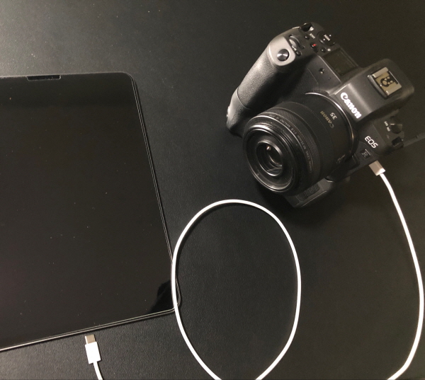
▲그림 1 : USB-C 케이블을 통해 디지털 카메라와 태블릿을 연결한 장면
■ USB-C PD 시스템
그림 2는 USB-C 케이블로 연결되고 리튬이온(Li+) 배터리로 구동되는 통상적인 휴대기기 전원 관리 시스템을 보여준다. VBUS가 제공되면 차저, 시스템, 나머지 블록들로 전원이 공급된다. 이러한 상황에서는 배터리가 충전된다. VBUS가 제공되지 않을 때는 배터리가 시스템으로 전원을 공급한다. USB-C 케이블은 CC1과 CC2 핀이 포트 연결, 케이블 방향, 역할을 인식하고 포트 제어를 담당한다. D+/D- 라인은 표준 USB-C 통신 라인으로서, 480Mbps 속도로 데이터를 처리하고 D+/D- 보호 디바이스를 사용해서 보호된다. PD 컨트롤러는 PD 프로토콜을 담당한다.
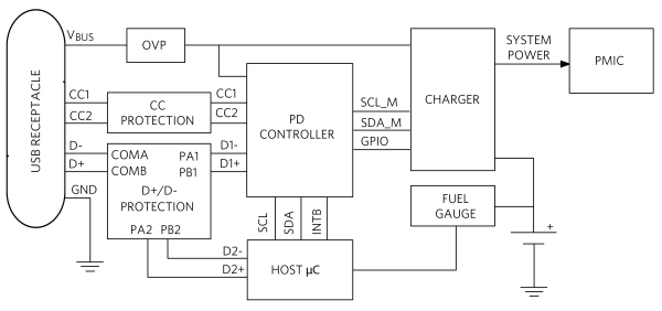
▲그림 2 : USB PD 전원 관리 시스템
■ 보호 기능과 관련한 과제들
전원 공급 장비 내에서 전기적 서지와 정전기 방전(ESD)은 만연한 것으로, 이들은 서로 간 방해를 일으킬 수 있고 또는 전자 부하와 장비에 손상을 입힐 수 있다. ESD는 인체에서 전자 회로로 정전기 전하가 전달되어서 발생되는 것으로서, 휴대형 전자기기에서 매우 중요하게 다루어야 할 과제이다. 서지(surge)는 낙뢰에 의해서 발생하거나, 또는 낙뢰 스트라이크 가까이에서 길게 이어진 케이블로 유도될 수 있다. 스위치나 릴레이가 온(on)과 오프(off)로 동작할 때도 서지가 발생할 수 있다. 부하 덤프는 자동차에서 배터리 연결이 차단되었을 때 발생하는 서지이다. 우수한 데이터 라인 보호 IC라면 데이터 전송을 방해하지 않으면서 적절한 보호를 제공해야 한다.
■ 고도의 통합 솔루션
MAX20334는 2 x SPDT 스위치로서, 휴대 전자기기의 과전압 보호용으로 사용하기에 적합하다(그림 3). 이 IC를 사용해서 하위의 데이터 라인을 고전압 단락, ESD, 서지 이벤트로부터 보호할 수 있다. MAX20334는 낮은 온(on) 커패시턴스와 낮은 온(on) 저항이 특징이다. 이 점은 휴대 기기의 고성능 스위칭 애플리케이션에서 중요하게 요구되는 특성이다. 또한 이 IC는 양(+)의 과전압 및 서지에 대한 보호 기능을 포함한다. USB low/full/high-speed 시그널링을 지원하고, 2.7V~5.5V 전원으로 동작한다. 12범프(1.23mm x 1.63mm) 웨이퍼 레벨 패키지(WLP)로 제공되며, -40℃~+85℃의 확장된 온도 범위에서 동작한다.
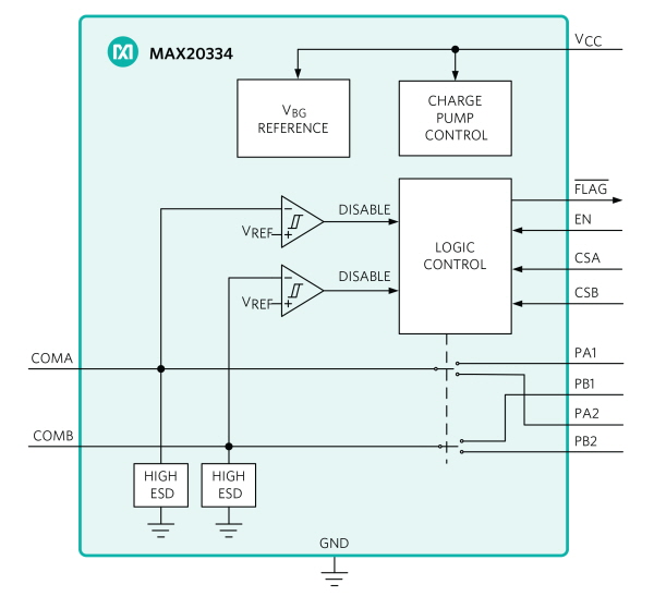
▲그림 3 : 포괄적인 보호 기능을 제공하는 2 x SPDT 스위치
■ 포괄적인 보호 기능 제공
이 IC의 모든 핀들이 ESD 보호 구조를 포함하고 있어, 핸들링 및 어셈블리 시에 2kV(인체 모델)까지 이르는 ESD 보호 기능을 제공한다. 더 나아가서 COMA와 COMB(그림 2와 그림 3)는 ±15kV(인체 모델), ±15kV(IEC 61000-4-2에서 정의한 에어갭 방전 기법), ±8kV(IEC61000-4-2에서 정의한 접촉 방전 기법)까지 더 큰 ESD에 대한 보호 기능을 제공한다. 이 ESD 구조는 정상 동작일 때나 디바이스가 파워다운일 때나 모두 높은 수준의 ESD를 견딜 수 있다. ESD 이벤트가 발생하더라도 이 IC는 래치업을 일으키지 않고 계속해서 작동한다. 또한 이 IC는 -30V~+45V(IEC61000-4-5)의 서지와 최대 +20.5V의 과전압을 보호한다.
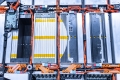
그림 4는 이 IC를 사용할 때와, 양(+)의 서지만을 보호하고 과전압(OV) 및 ESD 보호 수준이 더 낮은 경쟁 디바이스를 사용할 때의 PCB 레이아웃을 비교해서 보여준다. 후자의 경우에는 ESD/서지/OV 요건을 충족하기 위해 추가적인 회로가 필요하므로, BOM 비용을 증가시키고 PCB 면적도 5배 더 넓게 차지한다.
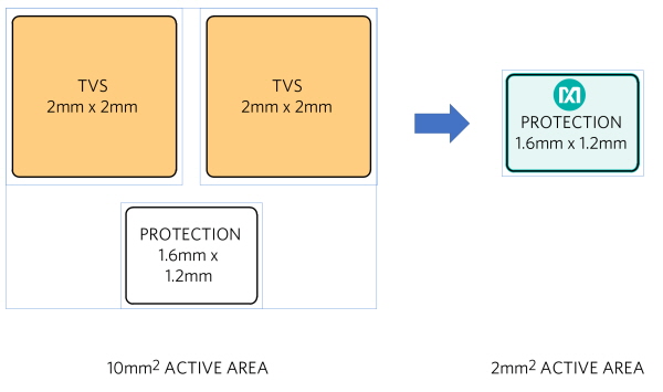
▲그림 4 : 통합 IC를 사용할 때의 이점
■ 데이터 무결성
그림 5의 아이 다이어그램(eye diagram)을 보면 데이터 신호의 무결성이 우수하다는 것을 알 수 있다. 둥근 파란색 선이 허용되지 않는 빨간색 영역으로부터 최대한의 거리를 유지하고 있다. 이 보호 IC의 높은 대역폭에 의해서 신호 상승 시간 및 하강 시간에서 최소한의 지연과 지터만을 일으키므로 오차에 있어서 상당한 마진을 확보할 수 있다. 이 점은 USB 적합성 테스트를 통과하는 데 있어서 중요하다.
.jpg)
▲그림 5 : D+/D- 아이 다이어그램
■ ESD와 전압 서지에 대해서 향상된 보호 필요
USB Type-C는 디지털 카메라나 울트라씬 태블릿 같은 전자기기들을 연결하고 전원을 공급하고 보호하는 데 새로운 과제를 제기한다. 이 새로운 커넥터는 USB Micro-B보다 핀 피치가 촘촘하므로 VBUS에 연결 시 단락의 위험성을 높인다. 또한 USB PD의 경우 전압이 더 높아짐에 따라 보다 견고한 보호가 필요해졌다. 뿐만 아니라 전자 부하들이 갈수록 더 복잡해짐으로써 ESD와 전압 서지에 대해서 향상된 보호가 필요해졌다. 이 글에서는 15kV ESD 보호, -30V~+45V 서지 보호, +20.5V 과전압 보호를 특징으로 하는 통합적인 보호 디바이스를 사용하면, 이것으로 데이터 라인을 보호하고, 보다 덜 통합된 디바이스 대비 더 적은 BOM과 더 작은 PCB 면적으로 ESD/서지/OV 요건을 충족할 수 있다는 것을 살펴보았다.
※ 저자 소개
나자레노 (레노) 로제티(Nazzareno (Reno) Rossetti)는 아나로그디바이스(Analog Devices)의 아날로그 및 전원 관리 전문가이다. 이 분야의 다수의 특허에 저자로 참여했다. 이탈리아 토리노 공과대학에서 전기공학 박사학위를 취득했다.
조쉬 프랑크하우저(Josh Frankhauser)는 아나로그디바이스(Analog Devices)의 산업용 및 헬스케어 사업부 매니저로서 산업용 통신 솔루션을 맡고 있다. UCLA에서 소재공학 석사학위를 취득했다.
관련뉴스
-

[기술기고]스태리 차이 ADI 매니저-Iq·최소 온 타임·EMI 낮은 車 PMIC
차량내 전원 공급과 관련해 상충하는 설계 과제들을 해결하고, 전력 설계를 간소화하기 위한 방안에 대해 스태리 차이 ADI 매니저에게 들어보는 자리를 마련했다.
2022-05-17 오전 9:37:06by 편집부
-
[기술기고]테이머 키라&나자레노 로세티 ADI-전기자동차 정션박스 설계 간소화 솔루션
새로운 전기 자동차(EV) 용량성 절연 데이지 체인 데이터 수집 IC가 어떻게 정션박스를 간소화하고 배터리 셀 전압 및 온도 측정과 시간 정렬을 달성하는지 알아본다.
2022-06-14 오전 11:47:52by 편집부
-

[기술기고]ADI 프레데릭 도스탈-전원공급 장치를 소형화 하는 방법
전원공급 장치 소형화에 대해 ADI 프레데릭 도스탈이 이야기한다.
2022-07-12 오후 4:01:41by 편집부


많이 본 뉴스
[열린보도원칙] 당 매체는 독자와 취재원 등 뉴스이용자의 권리 보장을 위해 반론이나 정정보도, 추후보도를 요청할 수 있는 창구를 열어두고 있음을 알려드립니다.
고충처리인 장은성 070-4699-5321 , news@e4ds.com