LED 백라이트 드라이버 디바이스의 전류를 조정하는 두 가지 방법을 간략히 살펴보고, 이 두 방법을 결합하여 사용할 수 있게 해주는 MAX25510 및 MAX25511의 활용 사례를 아날로그 디바이스(ADI) 기술진에게 들어본다.
“ADI MAX 시리즈, 하이브리드 디밍으로 EMI 감소”
MAX25510·MAX25511, DIM·ADIM 입력 동시 사용 구현
표준 PWM 디밍 제어·피크 LED 전류 설정 2개 신호 필요
■ MAX25510·MAX25511 최대 4개 LED 스트링 구동
이 글에서는 백라이트 고휘도 LED 드라이버에 디밍 신호를 적용하는 여러 방법을 설명한다.
MAX25510 및 MAX25511은 최대 4개의 LED 스트링을 구동할 수 있는 독립형 피크 전류 모드 제어 방식의 LED 드라이버이다. 4개의 통합 전류 출력은 각각 최대 120mA까지 싱크할 수 있으며, LED 전류 값은 트루 펄스 폭 변조(PWM) 디밍과 아날로그 디밍, 또는 이 두 가지를 결합한 하이브리드 디밍이라고 하는 방법을 사용하여 연속으로 조정이 가능하다.
그림 1은 MAX25510 및 MAX25511의 일반적인 애플리케이션 회로를 나타낸다.
트루 PWM 및 아날로그 디밍 기능은 적절한 주파수와 원하는 듀티 사이클의 구형파 신호를 앞서 언급한 디바이스의 DIM 및 ADIM 핀에 각각 주입함으로써 활성화된다. 하이브리드 디밍은 앞의 두 가지 방법을 결합한 것으로, 애플리케이션에서 전자기 간섭(EMI)을 줄이고 디밍 비율을 높이며 오디오 잡음을 줄일 수 있다.
아래에서 PWM 디밍, 아날로그 디밍, 하이브리드 디밍의 장단점을 간단히 살펴본다.
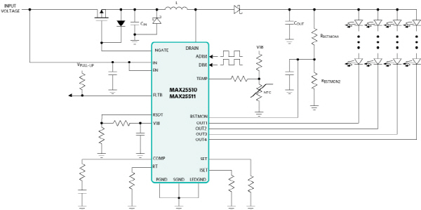
▲그림 1 : 일반적인 MAX25510-MAX25511 애플리케이션 회로(부스트 토폴로지)
트루 PWM 디밍은 디밍 신호의 프로그래밍된 주파수와 듀티 사이클에 따라 LED를 켜고 끈다. LED 피크 전류는 전체 디밍 범위에 걸쳐 일정하게 유지되므로 색 온도의 변화가 없고 광 출력에 큰 오차 없이 매우 낮은 최소 밝기 수준을 달성할 수 있다.
그러나 이 방법은 고휘도 영역에서는 취약하다. 고휘도의 경우, LED 전류가 켜져 있을 때 이 회로의 저항 소자로 인한 높은 전도 손실이 부하 전류 대비 효율에 영향을 미친다. 또한 세라믹 커패시터를 사용하는 경우, 출력에서 상당한 스위칭 잡음이 발생하며, 이로 인해 PWM 신호의 주파수가 가청 범위 내에 있으면 음향 잡음이 발생한다.
MAX25510 및 MAX25511은 DIM 핀에서 외부 PWM 디밍 입력을 추적하여 300ns의 최소 온시간으로 출력 펄스를 제공할 수 있다. PWM 디밍 주파수는 100Hz에서부터 디밍 비율을 너무 저하시키지 않는 값까지 가능하다.
■ 아날로그 디밍
아날로그 PWM 디밍은 PWM 입력을 취해 이를 아날로그 제어 신호로 변환한다. LED 피크 전류 값은 인가된 신호의 듀티 사이클에 따라 계수만큼 선형적으로 감소한다.
이 디밍 방법은 잡음을 저감해야 할 때 유리하다. LED 전류가 항상 연속적이고 고휘도에서 출력 세라믹 커패시터의 진동으로부터 발생하는 음향 잡음의 모든 가능성이 제거되기 때문이다. 또한 전도 손실이 낮아 낮은 밝기 레벨에서 부하 전류 대비 효율이 향상된다.
반면에 순전히 전류로만 제어될 때 LED의 비선형성으로 인해 최소 밝기 레벨이 제한된다. 이 때문에, 분해능 손실 없이 매우 작은 전류 값을 제공할 수 없다.
MAX25510 및 MAX25511은 ADIM 핀에서 가변 듀티 사이클로 구형파 신호(10kHz∼100kHz 주파수 범위)를 받아들임으로써 앞서 설명한 아날로그 디밍 기능을 구현한다. 그림 2는 ADIM 설정과 LED 전류의 관계를 보여준다(0% 듀티 사이클은 최대 LED 전류에 해당한다). ADIM 신호는 내부적으로 8비트 워드로 변환되며, 이는 256 밝기 레벨로 전환된다.
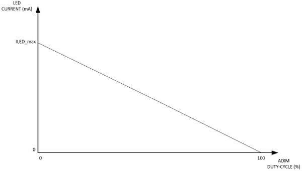
▲그림 2 : MAX25510 및 MAX25511의 아날로그 디밍 동작
■ 하이브리드 디밍
하이브리드 디밍은 LED 전류 제어를 두 부분으로 나누어 아날로그 디밍과 PWM 디밍의 장점을 결합한 것이다. 특히 하이브리드 디밍의 이점은 다음과 같다.
- PWM 디밍 시 낮은 전류 진폭으로 인한 EMI 감소
- 세라믹 출력 커패시터를 사용하는 경우 오디오 잡음 감소
- 더 높은 디밍 비율
고휘도 영역에서, LED 전류는 최대 디스플레이 밝기 레벨과 사전 설정된 전류 임계값 사이에서 선형적으로 변화한다. 임계값 이하에서, PWM 디밍은 신호의 듀티 사이클을 변조하여 밝기를 제어하면서 사전 설정된 피크 전류를 동일하게 유지할 수 있다.
MAX25510 및 MAX25511에 적용된 일반적인 하이브리드 디밍의 사례는 그림 3에서 볼 수 있다. 아날로그 디밍에서 PWM 디밍으로의 전환은 최대 LED 전류가 X배 감소하고 그에 따라 아날로그 디밍 듀티 사이클이 100*(X-1)/X배 증가할 때 일어난다. 그러한 전환이 일어나기 전에는 PWM 디밍의 듀티 사이클이 100% 유지되지만, 전환 후에는 100%∼0% 사이에서 임의적이다.
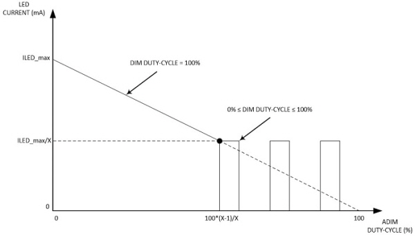
▲그림 3 : MAX25510 및 MAX25511의 하이브리드 디밍 동작
하이브리드 디밍은 MAX25510 및 MAX25511에서 DIM과 ADIM 입력을 동시에 사용하여 구현할 수 있다. 이를 위해 2개의 서로 다른 PWM 신호가 필요한데, 하나는 표준 PWM 디밍을 제어하는 신호이고(DIM 핀에 연결), 다른 하나는 ADIM 핀에 연결되어 피크 LED 전류를 0%∼100%로 설정하는 신호이다.
다음 예제는 MAX25511 IC를 탑재한 MAX25512 EV 키트로 하이브리드 디밍 동작을 보여준다.
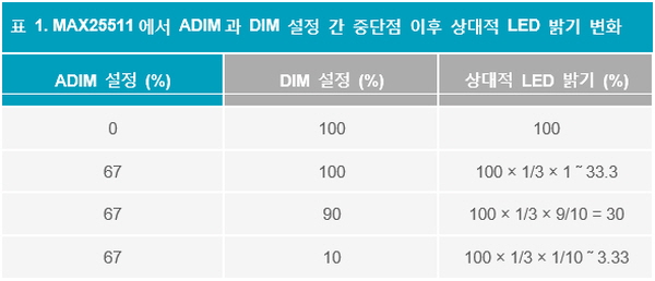
ADIM 핀에는 0%∼67%의 듀티 사이클로 10kHz 구형파 신호를 인가하면서 DIM 핀에는 1kHz-100% 듀티 사이클 구형파 신호를 유지하면, 스트링당 최대 100mA의 LED 전류가 33mA까지 선형적으로 감소한다. LED 전류가 33mA의 중단점 레벨에 이르면, DIM에서 신호의 듀티 사이클을 감소시켜 PWM 디밍을 통해 LED 밝기를 제어한다.
그림 4는 MAX25511 동작 회로와 실제 외부 부품 값을 보여준다. 이 디바이스는 위상 천이 기능이 비활성화되도록 구성되었다.
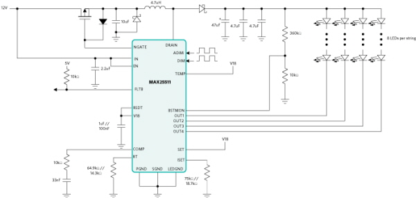
▲그림 4 : 하이브리드 디밍 테스트를 위한 MAX25511 동작 회로(부스트 토폴로지)
이 EV 키트로 수행한 벤치 테스트의 결과는 아날로그 디밍과 PWM 디밍 간 전환 과정의 여러 단계를 보여주는 다음의 오실로스코프 화면(그림 5∼8)을 통해 확인할 수 있다.
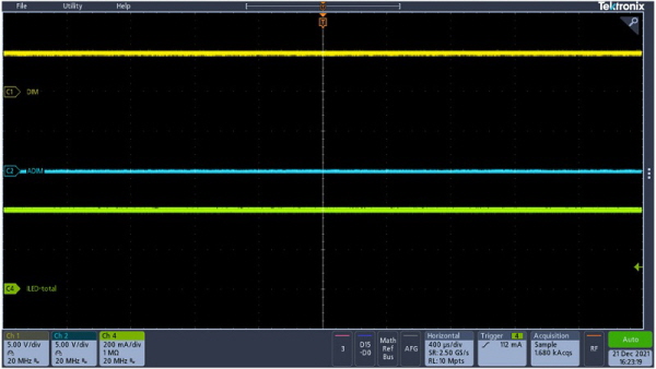
▲그림 5 : MAX25511 : ADIM 듀티 사이클 = 0%, DIM 듀티 사이클 = 100%, ILED_total = 400mA
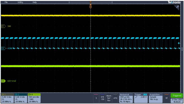
▲그림 6 : MAX25511 : ADIM 듀티 사이클 = 67%, DIM 듀티 사이클 = 100%, ILED_total = 132mA
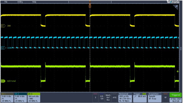
▲그림 7 : MAX25511 : ADIM 듀티 사이클 = 67%, DIM 듀티 사이클 = 90%, ILED_total (피크) = 132mA
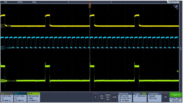
▲그림 8 : MAX25511: ADIM 듀티 사이클 = 67%, DIM 듀티 사이클 = 10%, ILED_total (피크) = 132mA
앞의 예제에서 ADIM 및 DIM 설정에 따른 상대적 LED 밝기 변화는 표 1에 요약되어 있다.
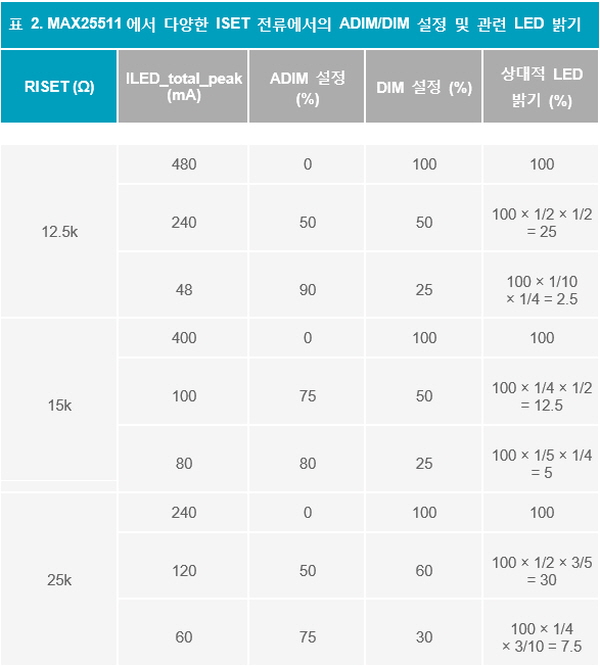
표 2는 총 LED 전류 및 관련 ADIM과 DIM 설정 측면에서 상대적 밝기의 더 많은 사례들을 보여준다.
■ MAX25510·MAX25511, 하이브리드 디밍 구현
지금까지 백라이트 LED 드라이버에 사용되는 PWM 디밍의 세 가지 주요 범주를 간략히 살펴보고, MAX25510 및 MAX25511이 전용 핀에서 트루 PWM 디밍 및 아날로그 디밍 신호를 통해 어떻게 LED 전류를 제어하는지 살펴봤다. 이 아키텍처를 활용하면 두 가지 디밍 방법을 결합한 하이브리드 디밍을 구현할 수 있다.
보다 자세한 내용은 MAX25510/MAX25511 데이터 시트 및 MAX25512 EVKIT 데이터 시트에서 확인할 수 있다.
※ 글
아나로그디바이스(Analog Devices, Inc.)