[기술기고]ADI 프레데릭 도스탈-“전원설계시 버스트 모드·펄스 스킵 확인 必”
기사입력 2022.02.15 10:50
“전원설계시 버스트 모드·펄스 스킵 확인 必”
버스트 모드 동작시 출력 전압 전압 리플 높아져
출력 전압 과도 상승차단 일부 펄스 건너뛸 수도
버스트 모드 동작시 출력 전압 전압 리플 높아져
출력 전압 과도 상승차단 일부 펄스 건너뛸 수도
 고정 스위칭 주파수를 사용하는 스위치 모드 전원공급장치라도 항상 계속적인 펄스 패턴을 나타내지 않을 수 있다. 때로는 다양한 이유로 펄스가 누락되어 보일 수 있다. 이는 출력 리플 전압 및 EMI와 관련해서 중요하다.
전압 변환을 위한 스위칭 레귤레이터는 가변 또는 고정 스위칭 주파수를 사용해서 동작한다. 스위칭 레귤레이터 IC의 데이터 시트 첫 페이지에 이 수치가 표기된다. 전원장치 회로에 어떤 스위칭 주파수를 선택할 것인가는 여러 면에서 중요하게 영향을 미친다. 이 선택에 따라서 외부 수동 소자들의 크기와 비용이 달라진다. 스위칭 주파수는 달성 가능한 변환 효율에도 영향을 미친다. 뿐만 아니라 스위칭 주파수 선택은 단지 전력 변환기뿐 아니라 전체 시스템의 다른 회로 부분에도 영향을 미칠 수 있다. 그러므로 전체 시스템에 방해를 최소화하도록 스위칭 주파수를 선택해야 한다. PCB 상의 기생성분들로 인해 전원장치의 스위칭 주파수가 시스템의 다른 부분들에 용량성 및 유도성 결합을 일으킬 수 있기 때문이다.
회로 설계자는 적정하다고 생각한 스위칭 주파수를 선택하여 실제 회로를 평가해보고 나서는 깜짝 놀랄 때가 있다. 설계된 회로가 선택한 스위칭 주파수에서 예상과 다르게 동작하는 것처럼 보일 수 있기 때문이다. 여기에는 두 가지 이유를 들 수 있다.
많은 애플리케이션이 극히 낮은 출력 부하에서도 높은 변환 효율을 요구한다. 필요한 출력 전력이 수 mW에 불과하면 스위칭 레귤레이터에서 공급 전류가 그에 비해서 너무 높을 수 있다. 효율을 퍼센트로 표기할 때는 이 문제가 특히 더 중요하다. 이러한 경우, 효율을 높이기 위해서 스위칭 레귤레이터 IC가 특수한 버스트 모드를 갖췄을 수 있다. 그림 1은 버스트 모드(Burst Modeⓡ)에서 스위칭 레귤레이터의 시간에 따른 전압을 보여준다. 스위칭 노드가 한 번 스위칭한 다음, 긴 정지 위상이 이어진다. 이 정지 위상에서는 스위칭 레귤레이터 IC의 많은 기능들이 슬립 모드로 전환하고 극히 적은 양의 에너지만을 필요로 한다. 그림 1에서는 스위칭 노드 전압, 인덕터 전류, 출력 전압을 볼 수 있다.
.jpg)
▲그림 1 : 스위치 모드 전원장치에서 버스트 모드(Burst Mode)의 컨셉트
버스트 모드로 동작할 때는 출력 전압의 전압 리플이 높아진다. 주파수는 정상 동작 주파수보다 훨씬 낮다. 전압 컨버터 IC와 회로 조건에 따라서 예컨대 하나의 펄스처럼 극히 적은 수의 펄스나 혹은 다수의 펄스를 사용해서 버스트 동작을 구현할 수 있다. 통상적으로, 출력 전압이 정해진 상단 임계에 도달할 때까지 필요한 수만큼의 많은 펄스들이 생성된다. 그러다가 출력 전압이 강하되어 최소 임계에 도달할 때까지 정지 위상이 이어진다. 이때에도 여전히 선택한 스위칭 주파수로 스위칭이 일어나고 있으나 스펙트럼 상으로는 버스트 위상과 정지 위상에 따라서 훨씬 더 낮은 주파수로 나타난다.
또 다른 경우는 펄스 스킵 모드이다. 다양한 전력 변환기들에 펄스 스킵 모드가 사용되는 것을 볼 수 있다. 많은 토폴로지 설계에서 스위칭 노드에 펄스가 발생될 때마다 최소 온(on) 시간에 따라서 전력 변환기의 입력 측에서 출력 측으로 특정한 양의 에너지가 전달된다. 이때 부하에 에너지가 필요하지 않거나 아주 적은 양만 필요하다면 출력 전압은 상승한다. 이럴 때 출력 전압이 과도하게 상승하는 것을 막기 위해서 일부 펄스를 건너뛸 수 있다. 이 경우에도 역시 출력 전압의 전압 리플이 높아진다. 피드백 노드에서 과전압 비교기에 의해서 펄스 스킵 모드가 작동된다. 예를 들어 매 두 번째 펄스를 건너뛴다면 스펙트럼(FFT 표현) 상에 나타나는 주파수는 설정된 스위칭 주파수의 절반이 될 것이다.
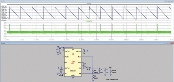
▲그림 2 : LTspice를 활용해 LT8620 스텝다운 스위칭 레귤레이터를 버스트 모드로 시뮬레이션했을 때
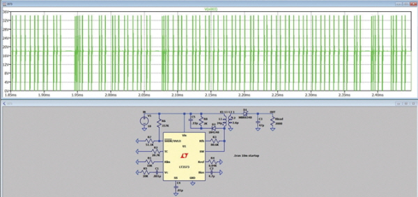
▲그림 3 : 저부하일 때 펄스 스킵 모드에 있는 LT3573
버스트 모드와 달리 펄스 스킵 모드는 출력 전압을 특정한 범위 이내로 유지하는 것만 하므로 그렇게 많은 양의 에너지를 절약하지는 못한다. 그러므로 변환 효율을 약간만 향상시킨다.
앞서 살펴본 바와 같이 스위칭 레귤레이터가 설정된 스위칭 주파수와 다른 주파수로 스위칭하는 것으로 나타난다면 이것은 버스트 모드나 펄스 스킵 모드 때문일 수 있다.
스위칭 노드에 불연속적인 펄스가 나타나는 데는 그 밖에도 다른 이유가 있을 수 있다. 예를 들어서 제어 루프 불안정성 때문이거나, 설정된 전류 한계에 도달했기 때문이거나, 혹은 열 셧다운 한계 이상으로 뜨거워졌기 때문일 수도 있다.
스위치 모드 전원장치는 설정된 스위칭 주파수와 다른 주파수의 펄스를 나타낼 수 있다. 이는 주로 낮은 부하 조건일 때 그렇다. 스위치 모드 전원장치 회로를 평가할 때 이러한 동작이 나타나는 메커니즘을 이해할 필요가 있다. 이를 통해 설계 엔지니어는 자신이 설계하는 전원장치가 안정적으로 동작할 것으로 확신하면서 설계할 수 있다.
※ 저자 소개
프레데릭 도스탈(Frederik Dostal) 아나로그디바이스(Analog Devices, Inc.) FAE는 독일 뉘른베르크 에를랑겐 대학에서 미세전자공학을 전공했다. 2001년 전력 관리 사업부에서 경력을 시작했으며, 애리조나주 피닉스에서 4년 간 스위치 모드 전원 공급장치를 담당하는 등 다양한 애플리케이션 직책을 맡았다. 2009년 아나로그디바이스에 입사하여 현재는 뮌헨 소재 아나로그디바이스에서 전력 관리를 위한 필드 애플리케이션 엔지니어(FAE)로 근무하고 있다.
관련뉴스
-
.jpg)
[기술기고]ADI 프레데릭 도스탈, “루프 대역폭 넓혀 출력 커패시터 수 감소”
전원장치 설계에서 출력 커패시터의 수와 크기를 최소화하는 방법에 대해 아나로그디바이스(Analog Devices, Inc.)의 프레데릭 도스탈(Frederik Dostal) FAE가 해법을 제시합니다.
2021-10-18 오후 5:02:13by 편집부
-
.jpg)
[기술기고]ADI 프레데릭 도스탈-“LT8330, 부스트·SEPIC 토폴로지 사용시 양의 피드백 핀 극성 必”
ADI의 LT8330을 사용한 ?uk 레귤레이터 회로설계시 유의점에 대해 ADI 프레데릭 도스탈이 해설한다.
2022-01-21 오후 4:01:33by 편집부


많이 본 뉴스
[열린보도원칙] 당 매체는 독자와 취재원 등 뉴스이용자의 권리 보장을 위해 반론이나 정정보도, 추후보도를 요청할 수 있는 창구를 열어두고 있음을 알려드립니다.
고충처리인 장은성 070-4699-5321 , news@e4ds.com