Techday
Physical AI HBM Smart Factory SDV AIoT Power Semicon 특수 가스 정정·반론보도 모음 e4ds plus

[Serial] ST Yuji Kawano Engineer (22) - Can a commercial power line (100V) be directly connected to an MCU terminal?

Google 우선 소스 기사입력2022.11.29 12:11

“When connecting MCU 100V, configure 3V·5V applied circuit”

Be sure to check the MCU GPIO specifications before calculating circuit constants.
Set a 10x margin to account for the possibility of short circuit failure

[Editor's Note] When we talk about semiconductors, we tend to think of semiconductors that are familiar to the general public, such as the CPU and memory of computers. On the other hand, MCUs (Micro Controller Units), which are core semiconductors used to operate electronic products, are semiconductors that are still unfamiliar to the general public, even though they are commonly used in all electronic products that we easily come across. These MCUs have recently been in the news due to the semiconductor shortage, and they are beginning to attract the attention of the general public. Accordingly, our magazine has prepared a place to learn about MCUs through a series of articles by Yuji Kawano, Manager of ST Microelectronics, a company specializing in MCU semiconductors.

■ Question

I want to modify the internal clock of the MCU using the frequency (50/60Hz) of the commercial power (100V), but using a voltage conversion adapter is too expensive. Can I connect the power line directly to the GPIO terminal of the MCU and use the commercial power frequency as an input signal?

■ Answer

MCUs typically use an operating voltage of 3V or 5V. Therefore, if a high voltage such as 100 V is applied to the GPIO terminal of the MCU, regardless of AC or DC, the MCU will be damaged.

For this reason, if you want to connect a commercial power line of 100V or higher to the MCU without a voltage conversion adapter, you must configure a circuit that uses a resistor to divide the high voltage and apply only 3V or 5V to the MCU terminals.

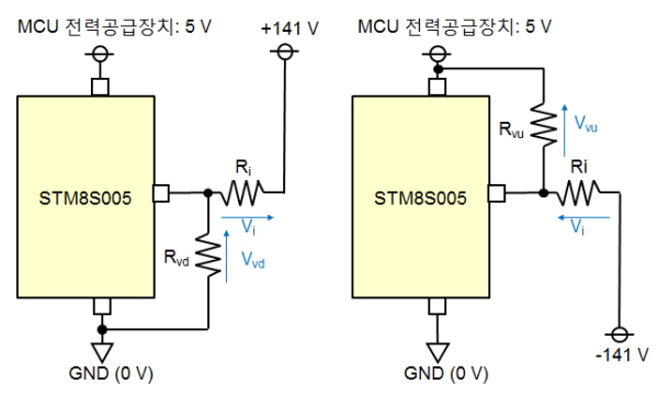
Figure 1 shows an example circuit using the STM8S005, an MCU manufactured by STMicroelectronics.

▲Figure 1: Example of a resistive voltage divider (using STM8S005)

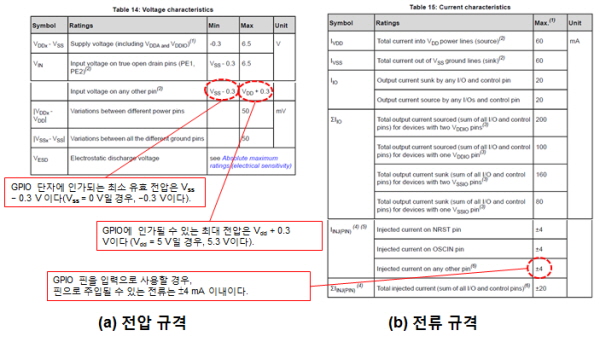
The datasheet provides a list of the currents that can be input to the GPIO terminal pins and the voltages that can be applied (Figure 2).

Current-limiting resistance values and voltage-dividing resistance values must be calculated to ensure that they do not exceed the specifications. When applying AC voltage, the resistance values and circuit configuration must be determined and the fact that negative voltages may be applied must be taken into account.

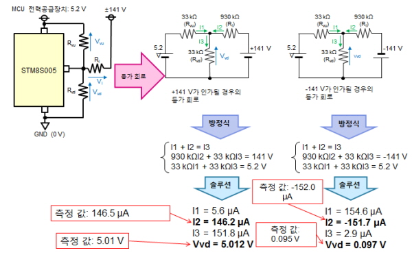
For Figure 1, when +141 V is applied, the GPIO terminal pin voltage is 5.012 V, but when -141 V is applied, it becomes 0.097 V. In this case, the currents passing through the current-limiting resistors are 146.2 μA and -151.7 μA, respectively, and even one of these currents must be input to the MCU terminal pin to meet the specification.

▲Figure 2: Absolute maximum rating value (based on STM8S005)

■ Notes

Each MCU's GPIO has its own specifications. In order to avoid exceeding the specifications, you must check the GPIO specifications of the MCU you want to use before calculating the circuit constants. In addition, this circuit is also affected by the specifications and configuration of the power circuit, so you must consider the power circuit when calculating the circuit constants. Incorrect circuit constants can cause the applied voltage to be too high, which can damage the MCU or adjacent circuits.

■ Description

○ Internal structure of GPIO terminal

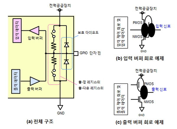
Figure 3 shows a typical GPIO structure. The GPIO circuit consists of an input buffer that receives input data, an output buffer that outputs output data, a pull-up/pull-down resistor that forcibly fixes the GPIO voltage, and a protection diode that diverts external surge voltage to the power supply or GND terminal.

When GPIO is used as an input terminal, the output buffer and pull-up/pull-down resistors are turned OFF, so it becomes a high impedance (HZ) state. If the applied voltage exceeds the power supply voltage or is lower than GND, one of the protection circuits turns on and allows current to pass, protecting the GPIO.

However, using a current that exceeds the current limit of the protection diode can damage the circuit. A list of these current values is given in Figure 2(b) as the injected current. This specification table indicates that the STM8S can tolerate a current of up to 4 mA. You must use the current-limiting resistor calculated to connect the GPIO terminal pins of this value.

Of course, applying high voltage to the GPIO terminal pins may cause malfunction.

The voltage-dividing resistance value must be calculated so that the applied voltage does not exceed the value shown in Figure 2(a).

Next, let's design a special circuit using STM8S005.

○ How to calculate current-limiting resistor and voltage-dividing resistor values

First, we will calculate the current-limiting resistor value. Assuming there is no voltage-divider resistor, let's set the current value that will not cause the MCU to malfunction even if the current is injected into the GPIO terminal pin.

Next, the resistance value must be determined to limit the current within the range of 4 mA, as shown in Figure 2(b).

When a positive voltage is applied to the terminal, a forward voltage is applied to the protection diode on the Vdd side, and the voltage difference between +141 V and Vdd (= 5 V), i.e., 141 V - 5 V = 139 V, is applied to the current-limiting resistor.

According to Ohm's law, if the resistance is greater than 139 V/4 mA = 34.75 kΩ, the current will be less than 4 mA. When the negative voltage is applied, the forward voltage is applied to the protection diode on the GND (Vss) side, and the voltage passing through the current-limiting resistor is 141 V.

If the resistance is set to 141V/4mA=35.25kΩ or more, the current will be less than 4mA (strictly speaking, the forward current of the protection diode should also be included in the calculation, but this is ignored in this article because it is much smaller than 141V).

Although these values will meet the specifications, it is best to set a margin of 10 times to account for the possibility of short-circuit failure. Also, one of these resistor values should always allow 4 mA of current. Since the current should be kept as low as possible considering the current consumed by the entire system, any further current reduction in the range of several μA is desirable. The larger the resistor, the easier it is to precisely adjust the value. In this example, we will use a resistor of about 1 MΩ.

▲Figure 3: GPIO structure

Next, let's calculate the voltage-dividing resistance value assuming that the current-limiting resistor has a value of about 1 MΩ.

The first case to consider is when +141 V is applied. In Figure 4(a), when +141 V is divided by Ri (current-limiting resistor) and Rvd (resistance between the GPIO terminal pin and GND), 5 V is applied to the GPIO terminal pin.

The following relationship must hold: Rvd/(Rvd + Ri)=5V/141V. This becomes Rvd/Ri=5/136=1/27.2.

In the lab, I found two resistors of about 1 MΩ that roughly represent this relationship: one was 33 kΩ and the other was 930 kΩ.

Therefore, if Rvd is 33㏀ and Ri is 930㏀, the relationship will be Rvd/Ri=33/930=1/28.1.

Next, we need to find the voltage-dividend resistor value that will apply approximately 0 V to the GPIO terminal pin when 141 V is applied.

We also need to consider the 0V point for the AC voltage. This means that when the applied AC voltage changes between +141V and +141V, it passes through the middle of 0V.

Since this 0V is the midpoint of the AC voltage, the voltage applied to the GPIO terminal pins should also be 1/2 at this point at the right time.

Therefore, the RVU (dividing resistance) to apply 141 V must be equal to RVD, i.e. 33 kΩ.

Based on this, the voltage difference of 5V+141V=146V is divided into RVU (=33kΩ) and RI (=930kΩ). Accordingly, VI=146V (33㏀/(963+33)㏀)=141V, and the voltage applied to the GPIO terminal pin is 141V+141V=0V.

The circuit shown in Figure 1 can be obtained as a result.

▲Figure 4: Resistive voltage divider circuit

○ Actual voltage and current value examples

To verify that the actual measured values match the design values, the circuit shown in Figure 1 was constructed.

A 5-VDC AC adapter was used to power the MCU, and the measured output voltage was 5.2 V. Under these conditions, the same circuit was configured for two cases where +141 V and 141 V were applied to the circuit, as shown in Figure 1.

The current value and the voltage value of the GPIO terminal pin in each mode were obtained from the simultaneous equations.

The detailed calculation formula is shown in Figure 5. The actual measurements matched the design values, confirming that the circuit was designed correctly.

I actually powered the STM8S005 with 100VAC and the circuit worked correctly without damaging the GPIO terminal pins.

▲Figure 5: Verification method of resistive voltage divider

○ Method of applying high DC voltage

When a high positive or negative DC voltage is applied instead of an AC voltage, only one dividing resistor is needed: RVD on the GND side for the positive voltage or RVU on the VDD side for the negative voltage. Since this article focuses only on the case where an AC voltage is applied, dividing resistors are used for both the positive and negative sides.

○ Additional explanation

Some GPIO specifications do not require a voltage-divider circuit, requiring only a current-limiting resistor.

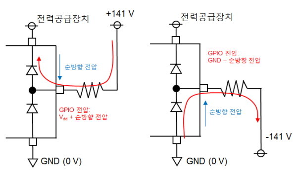
If only a current-limiting resistor (without a divider resistor) is used, the forward current will pass through the protection diode. The current-limiting resistor value must be calculated so that this forward current is less than the maximum allowable current that can pass through the protection diode. Since the forward voltage is generated through the protection diode, the GPIO pin voltage will be the Vdd+ forward voltage or the GND- forward voltage (Figure 6). The MCU can be used within the specification range without divider resistors as long as these voltages do not exceed the absolute ratings for the GPIO input voltages.

▲Figure 6: When there is no voltage-dividing resistor