고효율/고정 주파수 소형 스텝업 DC-DC 컨버터
다양한 애플리케이션에 통합 사용 가능
LED(Light-Emitting Diode) 정전류 구동회로로 최적화된 고효율/고정 주파수 소형 스텝업 DC-DC 컨버터는 1셀 및 2셀 알카라인, NiCd, NiMH 배터리로 작동되는 애플리케이션에 적합하며, 적은 수의 외부 소자로도 편리하게 전원을 공급할 수 있다. 이 컨버터는 1셀 알카라인이나 NiMH, NiCd를 사용해 구동되는 기본적인 단일 LED 드라이버부터 다중 적외선, 백색, RGB LED에 이르기까지 다양한 애플리케이션에 통합하여 사용할 수 있다.
이들 컨버터 중 하나인 마이크로칩의 MCP1643은 PWM(Pulse-Width Modulation) 전용 디바이스로서 고정 1MHz 스위칭 주파수로 동작한다. 그림 1은 이 디바이스를 사용한 간단한 DC-DC 전류 소스 스텝업 부스트 컨버터로, 원하는 전류를 설정하기 위해 저항(R
SET)을 사용한다.
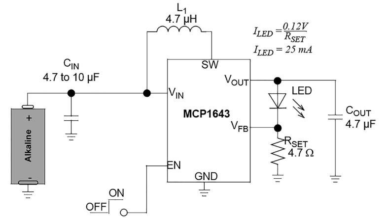
그림 1: 일반적인 스텝업 DC-DC 컨버터 애플리케이션
입력 전압에 따라 최대 LED 전류가 결정된다. MCP1643은 0.5V~5V 입력 전압과 0.65V 스타트업 전압으로 동작한다.
완전히 충전된 배터리의 경우 최대 정격 LED 전류는 450mA이다. 알카라인에 비해 NiMH와 NiCd 배터리는 공칭 전압이 더 낮으므로, 디바이스에 의해 공급되는 최대 LED 전류도 약 350mA로 더 낮아진다. 또한 배터리가 거의 고갈되더라도 최대 150mA를 계속 공급할 수 있다. 모든 LED 전류 드라이버와 마찬가지로, 최대 및 최소 부하 전류의 한계에 대해서는 몇 가지 제한 사항이 있다.
출력 LED 전류는 부스트 토폴로지 때문에 V
IN이 V
OUT보다 300mV~400mV 낮기만 하면 조정(regulation) 상태를 유지한다. 최대 부하 전류는 입력 전류 한계에 따라 결정되며, 이는 1.8A이다. 선택한 LED의 전류가 입력 전류를 이 디바이스의 최대 피크 전류보다 크게 끌어올리면, LED 전류가 조정 상태를 유지하지 못하고 입력 전압에 따라 변동하게 된다. 또한 배터리가 컨버터에 필요한 전류량을 유지할 수 있어야 한다. 이 디바이스가 조정할 수 있는 최소 출력 LED 전류는 20mA이다.
1셀 LED 드라이버: 가장 간단한 애플리케이션 중 하나는 검출 저항 값을 조절해 전류를 설정할 수 있는 정전류 LED 드라이버이다. 2.4W의 경우, 설정 전류는 50mA이며, 검출 저항을 병렬로 연결하면 이를 100mA 및 150mA로 높일 수 있다.
이 디바이스는 EN 핀에 인가된 가변적인 듀티 사이클 PWM 신호를 사용해 LED를 켜거나 끄는 방식으로 PWM 디밍을 할 수 있다. 최대 디밍 주파수는 보통 240ms의 내부 소프트-스타트 시간에 의해 제한된다. EN 입력에 인가되는 PWM 신호의 듀티 사이클을 다르게 하면, LED 평균 전류가 선형적으로 변하고 그에 따라 조명 세기가 변한다.
2개의 직렬 LED 드라이버: MCP1643을 사용해 2개의 직렬 LED를 구동할 수 있다. 하지만 출력 전압을 5.0V로 제한하는 과전압 보호 기능 때문에 최대 전압이 제한된다. 리모컨용 적외선 LED나 적색 LED와 같은 2개의 저전압 LED는 구동할 수 있지만 백색 LED나 청색 LED와 같은 고전압 LED를 구동하기는 어렵다.
병렬 LED 드라이버: MCP1643은 최대 출력 전류가 550mA이기 때문에 저전류 LED들을 병렬로 연결할 수 있다. 최대 LED 수는 컨버터의 최대 출력 전류(550mA)를 LED 전류 정격으로 나눈 값이다. LED 전류 정격이 50mA일 경우, 최대 11개의 LED를 구동할 수 있다. 동일한 값으로 같은 수의 저항도 필요하다.
LED와 저항을 한 쌍으로 사용해 디바이스로 전류를 설정할 수 있다. 이후 다른 쌍들은 첫 번째 쌍의 전류에 의해 제어된다.
이 애플리케이션은 LCD 조명을 위해 저전력 SMD 저항들을 일렬로 배열하는 휴대용 백라이트 디바이스에 적합하다. 이 기법은 비용이 저렴하고 소자 수가 더 적으므로, 큰 인덕터를 필요로 하며 PCB 공간을 많이 차지하는 고전압 정전류 부스트 컨버터를 대체할 수 있다.
MCP1643 DC-DC 컨버터는 고전력 RGB LED용 전류 소스와 마이크로컨트롤러용 전압 소스 모두로 사용이 가능하다. 1셀 AA 배터리를 사용해 전원을 공급할 수 있다.
RGB LED는 공통 캐소드 또는 애노드를 사용하는 3개의 LED(적색, 녹색, 청색)로 구성되며, 가시 스펙트럼 상의 모든 색을 구현하기 위해 동시에 또는 한 번에 하나씩 구동할 수 있다. 각각의 색마다 포워드 전압이 다르므로 각 LED를 개별로 구동하려면 전류 소스가 필요하다.
이 디바이스는 최대 출력 전류가 550mA이지만 하나의 출력만 제공한다. 따라서 3개의 LED를 개별적으로 구동하려면 마이크로컨트롤러를 사용해 제어해야 한다. 240ms의 소프트-스타트 시간을 사용할 경우 70Hz의 LED 주파수로 전류 오버슈트 없이 각 색상에 대해 출력을 멀티플렉싱 할 수 있다. 각 LED를 개별적으로 구동하기 위해서는 외부 트랜지스터를 통해 LED 전류 경로를 전환해야 한다.
이 애플리케이션에서는 짧은 시간 동안 디바이스를 전압 소스로 사용할 수 있다. LED와 피드백 저항을 차단하고 저항 디바이더를 사용해 피드백 전압을 제어하면 출력 전압을 정전압 4V로 높일 수 있다. 또한 이 디바이스는 3개의 LED도 구동하고 제어 시스템도 구동해야 하므로, 대략 300Hz(70Hz의 약 4배)의 주파수에서 칩이 구현될 수 있어야 한다.
다중의 개별 LED 컨트롤러로 사용하려면 동일 피드백 저항을 통해 한 LED에서 다른 LED로 출력을 이동해야 한다. 또, 제어 시스템이 전류 경로를 변경할 때마다 디바이스를 정지했다가 다시 동작시켜야 한다. 다른 LED 색상으로 변경할 때는 전류 오버슈트를 완전히 방지하기 위해 출력 전압을 낮춰야 한다. 그러려면 PIC 마이크로컨트롤러가 필요하다.
그림 2: 동작 원리
그림 2는 제어 신호 타이밍을 보여준다. 녹색, 청색, 적색 신호는 트랜지스터 게이트 전압이다. 이 트랜지스터를 사용해 각 색상의 전류 경로를 변경할 수 있다. 트랜지스터들이 명령 신호(게이트 전압)를 받으면, 전도를 통해 해당 색상의 LED가 LED 드라이버와 폐쇄 전류 루프를 형성하도록 한다. ‘인에이블(enable)’ 신호는 이러한 게이트 신호들과 동기화되고, LED가 제어되지 않을 경우는 추가적인 인에이블 간격을 가진다. 이 기간 동안 출력 전압이 정전압으로 상승하며, 디바이스가 전압 소스처럼 동작한다.
이 때 인에이블 신호의 순서에 주의를 기울이는 것이 중요하다. LED를 출력에 연결하지 않고 이 디바이스를 시작하면 출력 전압이 최대 5V로 상승하게 된다. 그런 다음 이 회로에 LED가 연결되면 출력 캐패시터가 통제를 벗어나 LED로 방전되고 이는 LED를 손상시킨다.
인에이블 신호들 간의 데드 타임은 포워드 LED 전압의 차이 때문에 다 다르다. 저전압에서 고전압으로 양의 전압 전이가 이뤄질 경우 데드 타임을 제거할 수 있지만, 이는 권장하지 않는다.
MCP1643은 전압 소스로 사용하기 위해서는 몇 개의 외부 소자가 필요하다. 피드백 저항을 전류 드라이버의 피드백 루프로부터 차단하기 위해서는 트랜지스터를 추가해야 하며, 피드백 루프의 저항 디바이더는 제어 시스템에 사용되는 적절한 수준으로 전압을 상승시킬 수 있다. LED가 연결되지 않은 상태에서 이 디바이스를 동작시킬 경우, 출력 전압이 단 시간에 약 4V로 증가한다.
멀티플렉싱으로 인해 PIC 마이크로컨트롤러 전압은 조정되지 않으며 멀티플렉싱 주파수, 저장된 에너지 양, 제어 시스템의 전력 소모에 따라 시간이 갈수록 떨어진다.
좀 더 조정된 전압이 필요할 때는 이 디바이스 다음에 LDO(Low-Drop Regulator)를 사용하면 된다. 3.3V 전원이 필요할 경우에는 MCP1702와 같이 정지 전류가 낮은 LDO 레귤레이터를 사용할 수 있으며, MCP1643의 출력 전압은 3.6V 이상으로 설정해야 한다. 그러면 2.3V~5V 전원 전압으로 동작하는 마이크로컨트롤러 기능에 전압 강하가 영향을 미치지 않게 된다.
또한 LED 제어 전압을 방해하지 않으려면 추가 소자들이 필요하다. 쇼트키(Schottky) 다이오드는 어떠한 전압도 LED로 역류하지 않게 해주며, 캐패시터는 디바이스가 LED를 구동하고 있을 때 에너지를 저장할 수 있다.
그림 3: RGB LED 드라이버 데모 보드의 전기 회로도
이 기법은 제어 시스템을 위해 별도의 DC-DC 컨버터가 필요하지 않다는 점 외에도 다른 장점이 있다. 컨버터가 턴오프되면 마이크로컨트롤러도 턴오프된다. 따라서 전체 시스템은 디바이스의 정격 1.2mA 셧다운 전류만을 소모한다.
이 시스템은 디바이스 동작(마이크로컨트롤러도 자동으로 켜짐), 또는 마이크로컨트롤러에 최소 100ms 동안 외부 전압 소스가 인가될 경우 수동으로 재시작할 수 있다.
PCB 레이아웃은 일반적인 DC-DC 컨버터 규칙에 따라 이루어져야 한다. 대부분의 전류를 전달하는 전원 PCB 패턴 라인은 최대한 짧게 해야 하며, 모든 검출 신호나 하이-임피던스 신호 패턴 라인 아래 혹은 가까이 지나가지 않도록 해야 한다. 스위칭 노드도 간섭을 줄이기 위해 되도록 짧게 해야 한다. 입력 및 출력 캐패시터는 컨버터에 최대한 가까워야 하고, 그라운드 플레인을 사용하는 것이 좋다.
MCP1643은 다목적 동기 부스트 DC-DC LED 드라이버 컨버터로서, 낮은 스타트업 전압 및 고전류 성능을 갖춘 단일 알카라인 배터리 전원 애플리케이션을 위해 설계되었다. 사용 중이 아닐 때는 대기(셧다운) 전류가 1.2mA로 낮기 때문에 배터리 수명을 연장해 주며, 필요한 외부 소자의 수가 적고 PCB 면적을 적게 차지하므로 소형 휴대기기 애플리케이션에 적합하다. 이 디바이스를 사용해 DC-DC 컨버터를 간편하게 구현할 수 있으며, 마이크로컨트롤러를 추가하여 디자인의 범용성과 편리성을 보다 높일 수 있다.