KITECH Webinar_~7.22
Physical AI HBM Smart Factory SDV AIoT Power Semicon 특수 가스 정정·반론보도 모음 e4ds plus

Q&A on improving antenna characteristics of embedded wireless communication, something engineers are curious about

Google 우선 소스 기사입력2019.08.11 16:41

In the case of wireless communication ICs, single-chip integration has been widely implemented, and antennas, such as chip antennas and antennas designed within PCBs, are being used. However, due to a lack of understanding of antennas that affect wireless performance, there are many cases where the results that consumers demand are not achieved.


As portable wireless communication devices have been increasing in recent years, the importance of wireless communication is also increasing.

When wireless engineers try to improve distance performance and direction-dependent transmit/receive characteristics in field tests , they often have difficulty figuring out where and how to debug.
The number of wireless devices continues to increase

As a purchaser and developer, it is difficult to know what specifications to look for when selecting an antenna and how to match the impedance of the antenna.

On the 6th, at the e4ds EEWebinar, Professor Park Kyung-jin of the e4ds Electrical and Electronic Lifelong Education Center held a webinar covering the meaning of antenna gain, radiation pattern analysis methods, and antenna impedance matching methods.

Below are some questions from webinar viewers about the design of the antenna and Professor Park Kyung-jin's answers.


Q. In what frequency bands are the antennas described in the webinar generally widely applied? (ID: yk**)
A. It is used from about 900MHz to 5GHz. However, the characteristic parameters can be generally applied to any antenna.


Q. What kind of antenna is efficient to use in cases where the frequency band is high and the linearity is strong, such as 5G? (ID: ho**)
A. Basically, antennas above 25GHz use a patch antenna form. The square PCBs are called elements, and increasing the number of them sharpens the beam width and increases the gain.
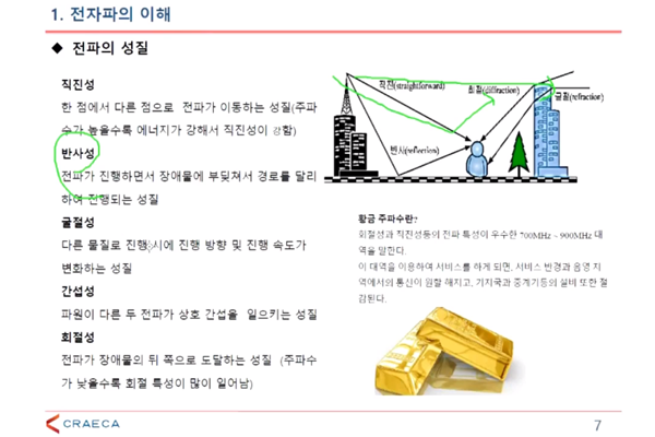
The nature of radio waves in the webinar content

Q. Does a straight-line radio wave lose power when there is an obstacle? Or is there a way to compensate? (ID: lc**)
A. Power loss occurs. There is no means of compensation. In some ways, something like a repeater can be seen as a means of compensation.


Q. I've always wondered about the antenna symmetry property . If the transmit and receive frequencies are separated and you want to improve the reception performance, there must be something that makes the receive side resonance better than the transmit side, so how can you say it has symmetry? (ID: gi**)
A. If the transmit antenna gain is 3dBi, the receive antenna gain is also 3dBi. The antenna shape, etc. are not changed. However, the receive side can be made to resonate better by using matching.


Q. When measuring with a network analyzer, can I get a Smith Chart even if I measure from one side? Usually, I measure from both sides. (ID: jw**)
A. Measure by biting both sides, but you can read either side separately.
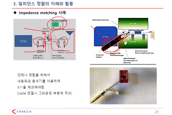
Impedance matching case from the webinar content

Q. If impedance matching is done, is there no loss in complete reflection? What ohm is usually used for impedance? (ID: lc**)
A. When impedance matching is achieved, there is no reflection and conditions are created for the signal to pass through well. The power transmission rate is improved and there will be almost no loss. The impedance is mainly used at 50 ohms.


Q. Why is the impedance matching 50 ohms? (ID: w3**)
A. 33 ohms is good for power transmission and 75 ohms is good for transmission of video signals. The value in between is defined as 50 ohms.


Q. Why is VSWR Voltage Standing Wave Ratio? (ID: ma**)
A. The concept of VSWR is that when a signal passes through an AC voltage, the incident wave and the reflected wave overlap and appear to be standing still. It is also called ISWR .


Q. How do you remove the antenna main beam and side beam to increase the received signal gain? Is it through signal processing? (lc**)
A. It can be adjusted to ground. The concept of signal processing can be adjusted using the concept of beamforming .
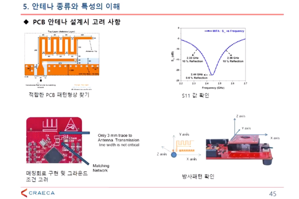
Webinar Content: Considerations for PCB Antenna Design

Q. Can I obtain the value by making the near field and far field characteristics different but with the same conditions? In other words, by applying the far field conditions to the near field conditions. (ID: lc**)
A. This is a story that comes up a lot when building an antenna chamber. It is also a factor that makes it difficult to miniaturize the chamber . The calculation can be converted, but there are many difficulties in actual implementation. In other words, you can think of the measured value as not being quantifiable.


Q. How can I prevent the antenna signal from going in a certain direction? (ID: na**)
A. You need to use the beamforming concept.
이수민 기자
기사 전체보기

1 Comments:

  1. 임*혁

    좋은 정보 감사합니다

임베디드 무선통신을 위한 안테나 이해와 활용
2019-08-06 10:30~12:00
전기전자 평생교육원 / 박경진 교수