PLL, VCO 위한 일종의 피드백 제어 시스템
주파수 합성 및 고주파 측정, 통신 등에 사용
ADF4150HV, RF 분할기로 더 넓은 대역 지원
위상 동기 루프(Phase-Locked Loop; PLL) 회로는 전압 제어 오실레이터(Voltage Controlled Oscillator; VCO)와 위상 검출기가 결합한 피드백 시스템으로서, 인가된 주파수 또는 위상 변조 신호를 오실레이터 신호가 정확한 주파수와 위상으로 추적하는 방식을 따른다.
고정된 저주파 신호로부터 더 높은 안정적 출력 주파수를 생성하고자 하거나 신속한 주파수 변경이 필요할 때 PLL을 사용한다. 대표적인 활용 사례로는 주파수 합성을 비롯해 고주파에서 필터, 변조, 복조를 위한 측정, 그리고 통신 등을 들 수 있다.
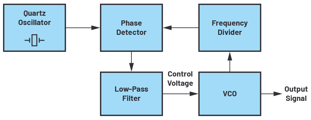
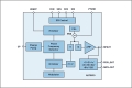
▲ [그림 1] PLL 회로의 블록 다이어그램
그림 1은 PLL 기반 주파수 합성기의 블록 다이어그램이다. 발생하는 신호는 레퍼런스 주파수로 동기화되며, PLL에 의해서 설정된 주파수로 유지되고, VCO에 의해 출력 신호가 출력된다.
이 레퍼런스 주파수는 정확도 높은 쿼츠 오실레이터를 사용해서 제공된다. PLL 회로의 피드백 경로 위에서 위상 검출기 앞 단에 주파수 분할기를 사용해서 VCO의 주파수를 가변 계수로 낮춘다.
VCO는 입력 전압에 따라 달라지는 커패시턴스를 사용하는 버랙터 다이오드 같은 가변 소자를 포함한다. 그러므로 PLL은 VCO를 위한 일종의 피드백 제어 시스템이다. 흔히 VCO에 요구되는 입력 또는 제어 전압은 PLL 회로에 이용할 수 있는 전원 전압보다 더 높다.
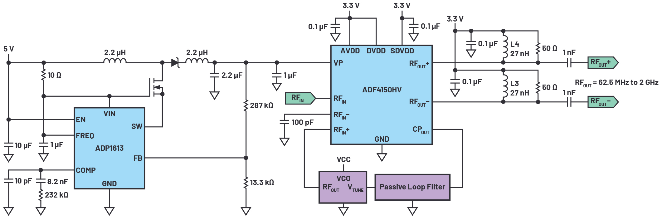
▲ [그림 2] ADF4150HV를 사용할 때
고전압 차지 펌프 전원 회로
전원 전압은 통상적으로 3.3V 또는 5V인데, VCO는 요구되는 주파수에 따라서 20V 이상의 전압이 필요할 수 있다. 더 넓은 범위의 주파수를 발생하기 위해서는 조절 범위가 더 넓은 VCO를 사용할 수 있다. 그림 2는 GHz 대의 VCO를 사용할 때의 회로를 예시한 것이다.
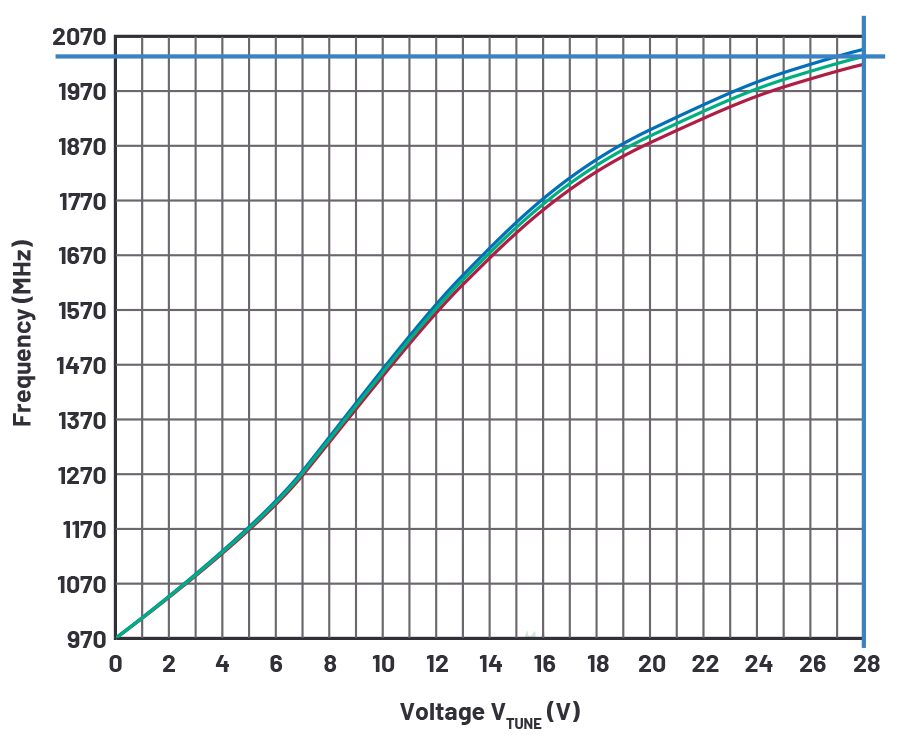
▲ [그림 3] DCYS100200-12의 제어 전압 대비 주파수
VCO로서 시너지 마이크로웨이브(Synergy Microwave)의 DCYS100200-12를 사용할 수 있다. 그림 3의 그래프에서 보듯이, 이 제품은 28V(V
TUNE)로 2GHz의 주파수가 가능하다.
높은 제어 전압을 발생시키는 방법은 여러 가지가 있다. 한 가지 방법은 능동 루프 필터를 사용하는 것이다. 이것은 기본적으로 고속 증폭기와 저역통과 필터로 이루어지며, 위상 검출기로부터의 출력 펄스(CP
OUT)를 깨끗한 DC 전압으로 성형한다. 또 다른 방법은 아나로그디바이스(ADI)의 ADF4150HV 같이 차지 펌프를 통합하고 있으면서 추가적인 능동 루프 필터가 필요하지 않은 PLL 주파수 합성기 제품을 사용하는 것이다.
두 방법 모두 고전압 전원을 필요로 하지만, ADF4150HV를 사용하면 필요한 부품 수를 줄일 수 있다. 또한, 능동 필터 증폭기로 인해 발생하는 왜곡과 위상 잡음을 피할 수 있다. 그뿐만 아니라 분수-N 또는 정수-N PLL 주파수 합성기를 구현할 수 있다. 그러므로 VCO 주파수를 1, 2, 4, 8, 16으로 나누고 최저 31.25MHz에 이르는 출력 주파수가 가능하다.
DC-DC 부스트 컨버터인 ADP1613을 사용하면 PLL 성능을 떨어트리지 않으면서 ADF4150HV의 내부 차지 펌프에 필요한 높은 전압을 발생할 수 있다. ADP1613은 전력 트랜지스터를 통합한 스위칭 레귤레이터로서, 최대 20V에 이르는 출력 전압을 달성할 수 있다. 외부 전력 트랜지스터 같은 부품을 추가로 사용하면 더 높은 출력 전압을 달성할 수 있다.
ADP1613의 스위칭 주파수는 650kHz ~ 1.3MHz까지 조절할 수 있어 우수한 과도 응답을 달성하고 잡음 필터링을 간소화할 수 있다. 대체로 1MHz 이상의 스위칭 주파수를 선택할 것을 권장한다. PLL 루프 필터를 통해서 스위칭 잡음을 낮추기 위해서다.
ADF4150HV를 사용하는 PLL 주파수 합성기 회로는 RF 분할기를 사용해서 넓은 대역(62.5MHz ~ 2GHz)을 지원할 수 있다. 동일한 PLL 하드웨어 설계를 가지고 시스템의 서로 다른 여러 하드웨어 플랫폼용으로 각기 다른 주파수를 발생할 수 있다. 하지만 설계에 다양한 VCO 타입이 요구된다면, 그에 맞는 루프 필터를 포함하는 것이 좋다. 이렇게 하면 PLL의 신뢰성 있는 작동을 보장할 수 있다.
출력 주파수 조절 범위가 비교적 넓고 그에 따라서 더 높은 출력 전력이 요구될 때는 ADF4150HV의 각각의 RF 출력에 소형 필터가 필요하다. 27nH 인덕터와 50Ω 저항을 함께 사용함으로써 3GHz까지의 주파수를 조절할 수 있다. 이 저항은 정해진 출력 임피던스를 제공한다. 더 낮은 인덕턴스를 사용하면 주파수 범위를 더 낮게 확장할 수 있다.
최근 단일 하우징으로 넓은 주파수 범위가 가능한 통합 솔루션(PLL, 필터, VCO 통합)도 출시되고 있다. 하지만 이러한 솔루션은 각각의 소자들이 가깝게 붙어있어서 원치 않는 커플링이 일어날 수 있다. 디스크리트 설계는 배치 간격이 있으므로 이러한 위험성을 최소화한다.
ADI는 HF 기능 블록 개발과 HF 신호 체인 시뮬레이션을 지원하기 위해 PLL 주파수 합성기 시뮬레이션 툴로서 ADIsimPLL™을 제공한다. 설계자는 이 툴을 사용하여, PLL 성능에 영향을 미칠 수 있는 모든 주요 비선형적 효과들을 시뮬레이트 할 수 있다. 주파수 합성 프로세스에서 발생하는 원치 않는 스퓨리어스 주파수가 그러한 예 중 하나이다.
이 기사는 ADI에서 필드 애플리케이션 엔지니어로 근무 중인 토마스 브랜드(Thomas Brand)의 「Driving the VCO of a High Voltage Phase-Locked Loop Frequency Synthesizer Circuit」라는 제목의 글을 정리한 것입니다.