[연재]ST 유지 카와노 엔지니어⑯-“디커플링 커패시터 PCB 배치, MCU 밀착 必”
기사입력 2022.03.15 11:28
“디커플링 커패시터 PCB 배치, MCU 밀착 必”
노이즈 감소·전원 전압 평활화, 회로 임피던스 낮아야
세라믹 커패시터, 높은 주파수 특성 노이즈 저감 우수
노이즈 감소·전원 전압 평활화, 회로 임피던스 낮아야
세라믹 커패시터, 높은 주파수 특성 노이즈 저감 우수
[편집자주]일반적으로 반도체라 하면 컴퓨터의 CPU와 메모리처럼 일반인에게 익숙한 반도체를 떠올리기 마련이다. 반면에 전자제품 구동을 위해서 핵심 반도체로 쓰이는 MCU(Micro Controller Unit)의 경우 일반적으로 우리가 쉽게 접하는 모든 전자제품에서 사용되고 있으면서도 일반인에게는 아직 낯선 반도체다. 이런 MCU가 최근 반도체 부족 사태로 인해 언론에 오르내리며, 일반인들에게 주목받기 시작했다. 이에 본지는 MCU 반도체 전문기업인 ST마이크로일렉트로닉스의 유지 카와노 매니저의 연재기고를 통해 MCU에 대해 전문적으로 알아보는 자리를 마련했다.
 ■ 바이패스 커패시터, MCU 방사 노이즈 감소·유입 노이즈 우회
MCU 전원 회로를 설계하고 있다. MCU 전원선 연결을 위해 권장되는 디커플링 커패시터 형태는 무엇이며, 이것들을 어떻게 연결해야 하는가?
MCU 전원선 연결을 위한 디커플링 커패시터는 바이패스 커패시터라고도 한다. 이것은 전원 단자와 GND 단자 사이에 삽입돼 MCU에서 방사되는 노이즈를 줄이고 유입 노이즈(incoming noise)를 우회시킨다. 또한 전압 리플을 차단하여 전원 전압을 평활화(smoothing)하는 데에도 사용된다(그림 1 참조).
일반적으로 세라믹 커패시터와 탄탈 전해 커패시터가 MCU 디커플링 커패시터로 사용된다. 크기가 작으면서 탁월한 주파수 특성뿐만 아니라 낮은 임피던스 특성을 제공하기 때문이다.
디커플링 커패시터는 가능한 한 MCU 전원 단자에 가깝게 배치된다. 어떤 크기의 커패시터를 어떤 단자에 연결해야 하는가는 MCU의 내부 전원 회로에 따라 결정된다. 권장되는 회로에 대한 정보는 관련 MCU의 사용자 매뉴얼 또는 애플리케이션 노트를 참고하기 바란다. 또한 MCU 제조업체의 평가회로 보드를 사용해 보다 많은 것을 학습할 수 있다.
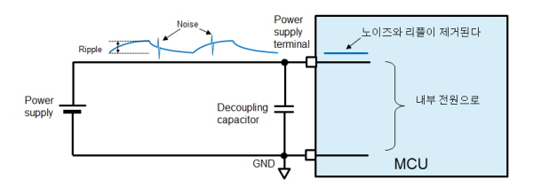
▲그림 1 : 전원선 상의 노이즈와 리플
■ 커패시터, 유전체 및 구조에 따라 구분
먼저, 커패시터의 기본적인 사항들에 대해 살펴보자. 적층 세라믹 커패시터(이 글에서는 ‘세라믹 커패시터’라고 한다), 탄탈 전해 커패시터, 알루미늄 전해 커패시터, 필름 커패시터 등 다양한 형태의 커패시터가 있으며, 이들은 그 유전체(dielectric materials) 및 구조에 따라 구분된다.
전해 커패시터는 대용량 전력 시스템(예를 들어, 전력 정류기)에 사용되며, 필름 커패시터는 안정적인 정전용량이 요구될 때(예를 들어 오실레이터 회로) 사용되며, 세라믹 커패시터는 넓은 주파수 영역을 담당할 수 있기 때문에 MCU 디커플링 커패시터로 사용된다.
정전용량 성분뿐만 아니라 실제 커패시터는 저항 및 유도 성분을 포함하고 있다. 세라믹 커패시터는 작은 저항 및 유도 성분을 가지고 있기 때문에 임피던스는 주파수가 상승함에 따라 낮아진다. 세라믹 커패시터는 노이즈 성분이 일반적으로 높은 주파수 특성을 가지기 때문에 노이즈 저감 특성이 우수하다.
다음은 실제 전원 회로의 설계에 대해 살펴보고, ST마이크로일렉트로닉스에서 생산하는 32비트 MCU인 STM32F2 시리즈를 예제로 몇 가지 예방 방법에 대해 설명한다.
ST 웹사이트에서는 다음과 같은 애플리케이션 노트를 제공하고 있다. ‘AN3320: STM32F20xxx/21xxx MCU 하드웨어 개발 방법 기초(AN3320: Getting started with STM32F20xxx/21xxx MCU hardware development)’. 대부분의 MCU 제조업체들이 이와 같은 문서를 제공하기 때문에 여러분이 사용하고자 하는 MCU 제조업체에 연락하면 어떤 커패시터를 선택해야 하는 지에 대한 정보를 얻을 수 있다.
위에서 언급한 ST 애플리케이션 노트의 경우, 디커플링에 관한 절에 특정 커패시터 형태와 정전용량 값에 대한 정보를 제공하고 있다. 여기를 살펴보면, “... 각 전원공급 쌍은 필터링 세라믹 커패시터(100nF)와 1개의 단일 탄탈 또는 세라믹 커패시터(최소 4.7?F에서 일반적으로 10?F)를 통해 디커플링되어야 한다...”라고 설명하고 있다. 이 절은 또한 그림 2에 나타낸 것과 유사한 회로를 권장한다.
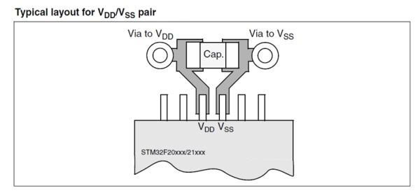
▲그림 2 : 디커플링 커패시터 회로를 위해 권장되는 레이아웃
이 절에서는 얼마나 많은 세라믹 커패시터가 필요한지에 대해서 설명하지 않지만, STM32F2 평가 보드(STM3220G-EVAL)에 대한 회로 다이어그램을 참조하여 이를 확인할 수 있다. 다이어그램을 살펴보면, MCU는 176개의 핀을 가지고 있으며, 이중 14개가 전원 단자이며, 15개의 100nF 세라믹 커패시터와 1개의 4.7?F 탄탈 전해 커패시터가 이것에 실장된다. 이것은 최소한 1개의 커패시터가 단일 전원 단자에 연결되어야 한다는 것을 의미한다. 보다 작은 수의 핀을 가진 패키지를 사용할 경우, 핀 수에 맞춰 세라믹 커패시터의 수를 줄여야만 한다.
노이즈 유형과 전원 전압 변동 특성이 전체 사용자 시스템에 대해 동일하게 나타나지 않기 때문에 MCU 제조업체가 권장하는 회로를 반드시 그대로 사용할 필요는 없다. 단지 참고용으로 제공되었을 뿐이다. 결국 여러분이 사용하는 설계는 여러분이 결정해야 한다.
디커플링 커패시터를 실제 인쇄 회로 기판(PCB)에 배치할 경우, MCU에 가능한 한 가깝게 배치해야 한다는 것을 명심해야 한다. 그림 3은 STM32F2 시리즈를 위한 LQFP64, 64핀 패키지에 대한 예제 레이아웃이다.
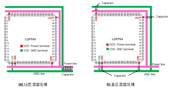
▲그림 3 : 커패시터 정렬의 예
전자 회로 다이어그램에서 모든 디커플링 커패시터는 일반적으로 전원 공급 영역에 대해 배타적으로 연결된다. 하지만 이것은 실제 PCB의 단일 위치에 이들을 함께 실장해야만 한다는 것을 의미하지는 않는다(그림 3(a) 참조). MCU 전원 단자에 가능한 한 가깝게 이들을 배치하면 된다(그림 3(b) 참조).
BGA(ball grid array) 패키지의 경우, 단자가 MCU 아래에 배치된다. BGA 패키지를 사용할 경우, MCU에 가능한 한 가깝게 이들을 배치하기 위해서 디커플링 커패시터를 보드 반대편(예를 들어, MCU의 정반대편)에 실장할 것을 권장한다.
■ 기타 고려사항 및 참고 정보
(1) 내장 레귤레이터를 위한 커패시터 평활화
오늘날 MCU는 내장 전압 레귤레이터를 통합하고 있으며, 대부분의 내부 회로가 MCU 전원 전압보다 낮은 전압 조건으로 동작한다. 이와 같은 경우, 실제 MCU 내부 회로의 전원은 내장 레귤레이터 출력 전원선이다. 일부 MCU는 레귤레이터 출력 전압을 평활화시키는 외부 커패시터를 위한 특수 핀을 제공한다. 그럼에도 레이아웃에 대한 기본적인 접근법은 관련 MCU 사용자 매뉴얼에 따라서 양호한 주파수 특성과 낮은 임피던스 특성을 가진 커패시터(예를 들어, 세라믹 커패시터 및 탄탈 전해 커패시터)를 MCU 단자에 가깝게 배치하는 것이다(그림 4 참조).
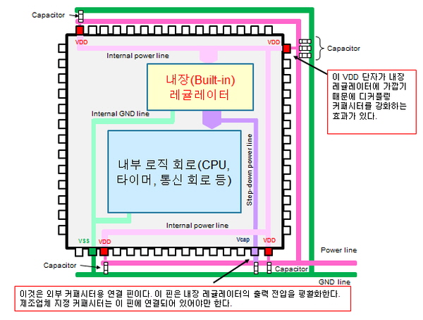
▲그림 4 : 내장 레귤레이터의 사용
(2) 내장 레귤레이터에 가장 가까운 전원선 상의 전원 단자
MCU가 여러 개의 전원 단자 핀을 가지고 있을지라도 대부분의 경우에 내부 전원 회로는 내장 레귤레이터 입력에 연결된다(주의할 것은 이것이 모든 MCU에 적용되지는 않는다는 것이다. 이를 확인하기 위해서 관련 MCU 제조업체에 연락하여 보다 자세한 정보를 구해야 한다). 어떤 전원 단자가 내장 레귤레이터 입력에 가장 가까운지를 알고 있다면, 보다 크거나 더 많은 수의 커패시터를 다른 단자들이 아닌 해당 단자에 연결하는 것이 노이즈를 줄이고 전원 전압을 평활화하는 데 있어 보다 양호한 결과를 제공할 수 있다(그림 4 참조).
MCU 제조업체에 문의하면, 기꺼이 여러분에게 어떠한 전원 단자가 내장 레귤레이터에 가장 가까운지에 대한 정보를 제공해 줄 것이다. 대안으로, MCU 제조업체의 애플리케이션 회로 중 하나에서 보다 많은 커패시터를 사용하는 전원 단자를 식별할 수 있다면, 그 단자가 내장 레귤레이터 입력에 가장 가까운 것이다.
관련뉴스
-

[연재]ST 유지 카와노 엔지니어⑬-“RTOS 지정된 시간 범위 내 처리 완료”
MCU는 CPU나 GPU와 다르게 낯설지만, 가장 많이 사용되는 반도체 중 하나다. ST 시스템 솔루션 랩의 유지 카와노 매니저에게 MCU의 활용성과 가능성이 얼마나 큰지 들어보자.
2022-02-15 오후 12:08:27by 편집부
-

[연재]ST 유지 카와노 엔지니어⑭-“CISC·RISC, 필요에 적합한 MCU 선택”
MCU는 CPU나 GPU와 다르게 낯설지만, 가장 많이 사용되는 반도체 중 하나다. ST 시스템 솔루션 랩의 유지 카와노 매니저에게 MCU의 활용성과 가능성이 얼마나 큰지 들어보자.
2022-02-22 오전 8:48:22by 편집부
-

[연재]ST 유지 카와노 엔지니어⑮-“발진소자 내장 MCU, 소자 특성 일치 必”
MCU는 CPU나 GPU와 다르게 낯설지만, 가장 많이 사용되는 반도체 중 하나다. ST 시스템 솔루션 랩의 유지 카와노 매니저에게 MCU의 활용성과 가능성이 얼마나 큰지 들어보자.
2022-03-08 오전 10:55:55by 편집부

.png)

관련 웨비나


많이 본 뉴스
[열린보도원칙] 당 매체는 독자와 취재원 등 뉴스이용자의 권리 보장을 위해 반론이나 정정보도, 추후보도를 요청할 수 있는 창구를 열어두고 있음을 알려드립니다.
고충처리인 장은성 070-4699-5321 , news@e4ds.com