가전기기에 대한 효율성, 전자기 간섭 감소 요구 증가
개발 제품 특성에 맞는 드라이버 제어 기법 선택 중요
환경 보호와 에너지 절약에 대한 인식이 그 어느 때보다 높은 시기다. 최근 냉장고, 세탁기, 에어컨 등의 대형 가전기기들은 시장의 효율성 증대와 전자기 간섭 감소 요구에 직면했다. 타깃 시장의 변화를 빠르게 수용하고, 제품 개발 시간을 확연히 단축하려면, 시스템 유연성이 높아야 한다. 동시에 개발자는 시스템 비용을 낮춰야 하는 과제를 부여 받는다.
비용과 효율성 측면에서 브러시리스 DC(BLDC) 모터는 가전기기에 점점 더 많이 사용되고 있다. 이 모터는 흔히 냉장고, 세탁기, 에어컨 등에 사용된다. 브러시드 DC 모터 및 AC 모터와 달리, BLDC 모터는 다양한 방법으로 구동 할 수 있다. 각 방법의 장단점을 자세히 알아보자.
BLDC 드라이버 제어 기법
BLDC 모터의 전자식 정류기는 순서대로 U위상이 되고 V위상이 되고 W위상이 되어서 스테이터 코일로 에너지를 공급하면, 회전하는 전기장을 발생시키고, 이것은 가까이에 있는 로터를 끌어당긴다. 효율적인 동작을 위해서는 스테이터와 로터의 상대적인 위치에 따라서 코일들에 정확히 에너지를 공급해야 한다. BLDC 모터는 로터 위치 피드백을 위해서 센서 또는 센서리스 피드백을 사용한다.
센서 설계에서 모터 스테이터의 가까운 위치에 3개의 홀 효과 센서 IC를 탑재한다. 홀 센서 IC의 전이 타이밍은 역기전력(BEMF) 제로 크로싱에 해당된다. 센서리스 방식은 모터 BEMF 제로 전압 크로싱 타이밍을 사용한다.
많은 애플리케이션이 센서리스 드라이버로 전환하고 있다. 이렇게 하면 모터 설계에서 홀 효과 센서 IC와 관련된 회로를 제거할 수 있기 때문이다. BEMF는 시작 시 BEMF가 0인 속도 함수이다. 센서리스 설계는 BEMF를 감지할 수 있는 속도로 모터를 가속하기 위해 복잡한 개방 루프 스타트업 알고리즘을 필요로 한다. 홀 정류 드라이버는 로터 위치를 항상 감지할 수 있으므로 스타트업을 신뢰할 수 있다. 대신 모터 어셈블리로 비용을 추가시킨다.
전자식 정류에는 다음과 같은 3가지 제어 방식을 사용할 수 있다:
• 사다리꼴(Trapezoidal): 사다리꼴 기법은 2개 위상으로 에너지를 공급한다. 한 위상은 모터로 전류를 공급하고, 다른 하나는 전류 리턴 경로를 제공한다. 나머지 위상은 구동하지 않는다. 2개 능동 코일로 에너지를 공급하기 위해서 3상 드라이버의 2개 스위치를 양이나 음으로 제어해야 한다. 모터가 회전함에 따라 모터 단자로 공급되는 전류는 매 60도 회전마다 정류된다.
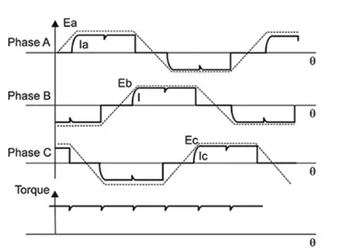
그림 1: 사다리꼴 제어 및 토크 리플
사다리꼴 기법의 장점은 구현하기 쉽다는 것이다. 단점은 이러한 계단식 정류로 인해서 토크 리플을 발생시킨다는 것이다. 토크 리플은 속도 변화를 일으켜 진동이나 가청 잡음을 유발할 수 있다.
• 사인파(Sinusoidal): 순수 사인파 구동 전압은 실제 설계에는 거의 사용되지 않는다. 각기 모터 단자로 접지와 비교해서 충분한 전압을 제공하지 못하기 때문이다. 더 나은 방법은, 정류를 위해서 120도 위상 편이로 “새들(saddle)” 프로파일을 사용해서 접지에 대해서 PWM 듀티 사이클을 변화시키고 구동 전압을 변화시켜서 위상들 사이에서 사인파 차동 전압을 발생시키는 것이다.
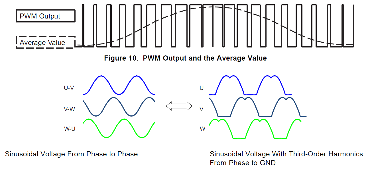
그림 2: “새들” 프로파일을 사용한 사인파 제어
결과적으로 모터를 구동하기 위한 위상 전류는 위상-대-위상 전압의 순수한 사인파 형태를 따른다. “새들” 프로파일 기법의 장점은 2가지다. 첫째는 최대 차동 전압은 순수 사인파 신호가 발생시킬 수 있는 것보다 높으므로, 주어진 입력으로 더 높은 토크와 속도를 제공한다. 둘째는 각기 단자 출력이 1/3의 시간 동안 0이므로 전원 스테이지에서의 스위칭 손실을 더 낮출 수 있다.
• FOC(field-oriented control): FOC 제어 기법은 그림 3과 같이 벡터로 시각화할 수 있는 2개의 직교 성분으로 3상 AC 전기 모터의 스테이터 전류를 결정한다. 이것을 시각화한 것이 그림 3이다.
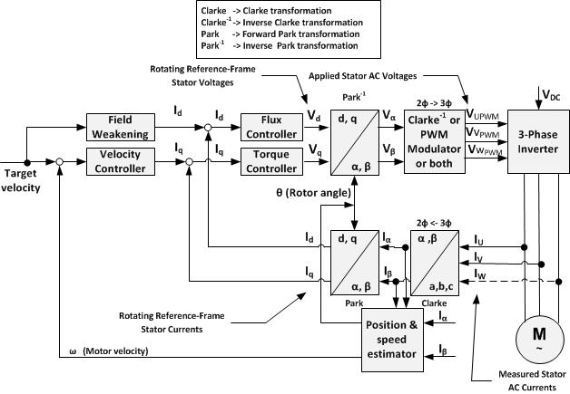
그림 3: FOC 제어 원리
하나는 모터의 자속을 결정하고, 다른 구성 요소는 토크를 결정한다. 드라이브의 제어 시스템이 드라이브의 속도 제어에 의해서 주어진 자속과 토크 값으로부터 해당 전류 값을 계산한다. 전류 비례 적분(PI) 제어 기법을 사용해서 드라이버의 PWM 출력을 제어한다.
위에서 세 가지 제어 기법을 살펴보았다. FOC는 모터 토크를 추적하기 위해서 복잡한 산술 연산을 수행하며 고성능의 마이크로컨트롤러(MCU)를 필요로 한다. 사다리꼴 제어는 BEMF 감지 아날로그 회로로 쉽게 구현할 수 있지만, 매 정류마다 토크 리플과 잡음을 발생시킨다. 사인파 제어는 정류 시 BEMF를 계산하는데, 부하가 갑자기 바뀌면 계산이 실패한다. 표 1은 세 가지 기법을 비교하고 있다.
| Control method |
Arithmetic |
Cost |
Torque ripple |
Audible noise |
Load response |
| Trapezoidal |
Easy |
Low |
High |
High |
Middle |
| Sinusoidal |
Middle |
Low |
Low |
Low |
Low |
| FOC |
Complex |
High |
Low |
Low |
High |
표 1: BLDC 모터 제어 기법 비교
가전기기는 배수펌프나 팬의 부하가 안정적이다. 따라서 가격대가 저렴하며 토크 리플과 가청 잡음이 낮고, 응답 시간이 짧은 사인파 제어 기법이 적합하다. TI의 DRV10987 BLDC 모터 드라이버는 세탁기 배수펌프와 건조기 팬에 사용되는 50W BLDC 모터 용의 단일 칩 사인파 솔루션이다. 사인파 제어는 잡음을 최대 13dB까지 감소시키고 효율을 최대 10%까지 향상시킨다. (“DC 모터 – 배수 펌프 데모”
영상 보기)
DRV10987은 제어 로직과 MOSFET을 통합하였다. 아날로그 전압, PWM, 또는 I2C 인터페이스를 통해서 모터를 제어할 수 있다. DRV10987을 사용함으로써 소형 폼팩터로 조밀한 드라이버를 설계할 수 있다.
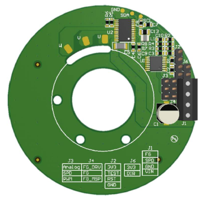
그림 4: 폐쇄 루프 속도 제어를 사용한 24V 36W 센서리스 BLDC 모터 드라이브 레퍼런스 디자인
그림 4는 폐쇄 루프 속도 제어를 사용한 24V 36W 센서리스 BLDC 사인파 모터 드라이브 레퍼런스 디자인으로서, DRV10987을 사용해서 폐쇄 루프 속도 제어를 구현하는 것을 보여준다.
DRV10987은 세탁기나 냉장고와 같은 가전기기의 견고한 모터 드라이버 제어 달성을 위해 필요한 포괄적인 보호 로직을 포함한다. 과전류 보호 회로는 위상-대-위상, 위상-대-GND, 위상-대-VCC 단락 회로 보호를 수행한다. 또한 전류 제한 로직을 포함하므로 위상 전류를 MOSFET의 피크 전류 능력(3A) 이내로 제한할 수 있다. 로터 록(rotor-lock) 감지 기능은 위치 소실과 로터 록 조건을 빠르고 정확하게 감지할 수 있다. 전압 서지 억제(AVS), 과전압, 저전압 보호 기능은 DC 버스 결함으로 인해서 칩이 손상되는 것을 방지한다. 또한, 과열 보호 기능을 포함하므로 과열로 인한 손상을 방지한다. DRV10987을 사용함으로써 특정 가전기기에 필요로 하는 모터 드라이버 보드를 짧은 시간 안에 손쉽게 개발할 수 있다.
어떻게 하면 고효율 고성능 BLDC 모터 드라이버 보드를 손쉽게 설계할 수 있는지 살펴보았다. 사인파 센서리스 BLDC 모터 드라이버를 사용하면 토크 리플이나 가청 잡음 문제를 해결한 우수한 가전기기 애플리케이션을 달성할 수 있다.
본 기사는 텍사스인스트루먼트의 기고를 바탕으로 작성되었습니다.