정전기의 기본 개념과 발생 원리 및
다이오드 기반 정전기 대책 숙지 필요
정전기는 대지와 절연된 물체 등에 마찰, 박리 등에 의하여 전하가 충전되는 현상이다.
순간 전류는 수 A에 달하지만, 실제로 전기가 흐르는 건 매우 짧은 시간이므로 정전기로 상처를 입는 경우는 거의 없다. 하지만 정전기로 전자 부품, 반도체, 제품은 쉽게 손상을 입고 더 나아가 화학 물질의 경우 폭발로 이어질 수도 있다.
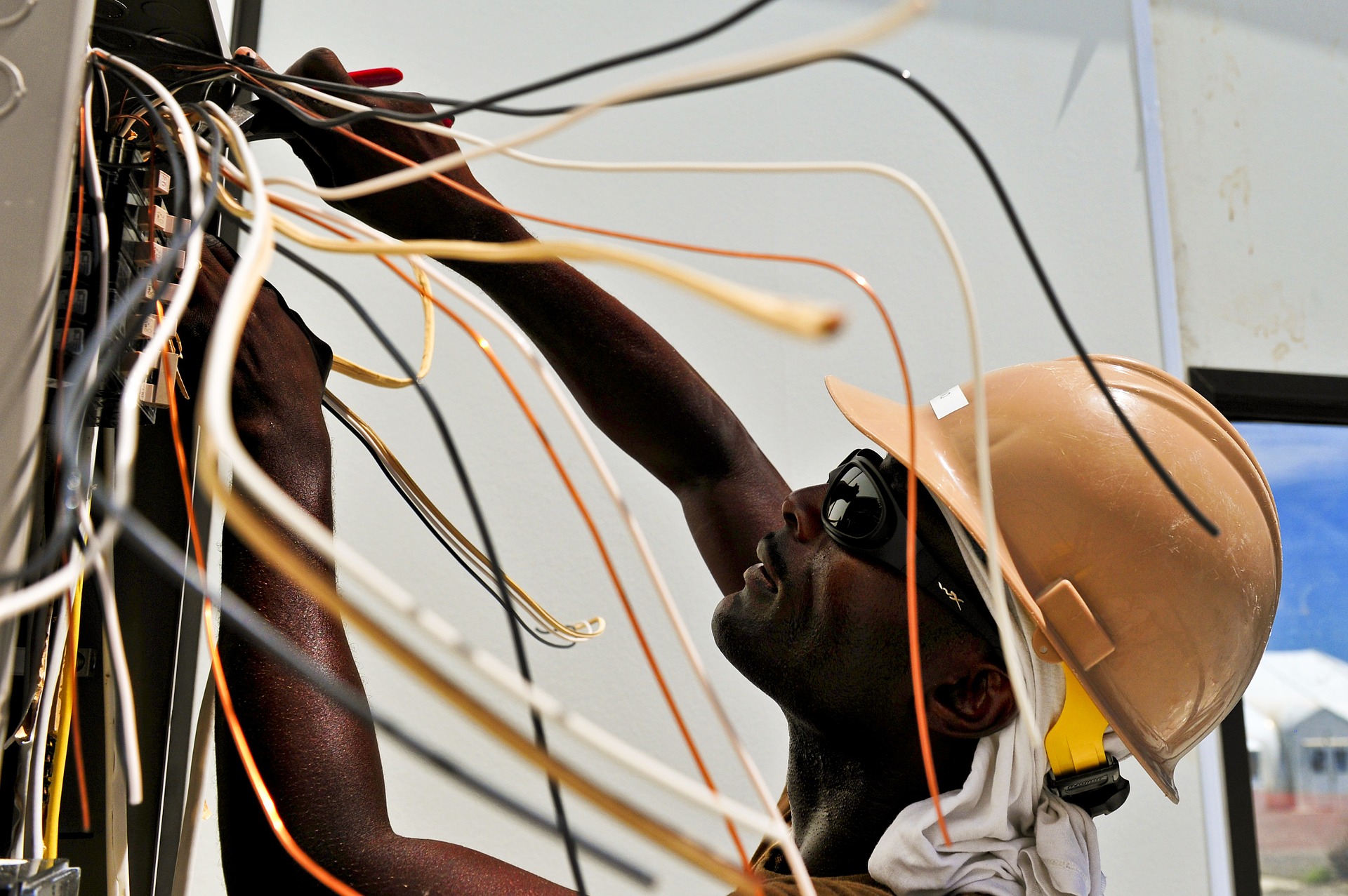
▲ 정전기를 이해하지 못하면 큰 사고로 이어질 수 있다.
따라서 회로설계자뿐만 아니라 공장/설비 관리자까지 정전기에 대해 폭넓게 이해하고 있어야 한다. 그래야 사고를 미연에 방지해 제품의 손상을 막고 폭발로 인한 재해를 막을 수 있다.
기사를 통해 정전기의 기본 개념과 발생 원리, 그 외 펄스성 전압원들에 대하여 살펴보고 이들이 어떤 특성이 있는지 다이오드를 기반으로 한 정전기 대책 방법을 알아보자.
전기장의 이해
마찰전기는 기원전 600년경 그리스의 탈레스가 장식용 호박을 닦다가 먼지가 달라붙은 현상을 관찰함으로써 발견됐다.
물질 속 (+)전하와 (–)전하의 총량은 평소에 중성이다. 그런데 두 물질을 마찰하게 되면 한 물질에서 다른 물질로 전자가 이동한다. 이 때 물질 내부에 움직이지 않고 있는 상태의 전기를 정전기라고 부르며 회로를 구동하기 위한 전류와 본질적 차이는 없다.
방전은 절연체에 전하가 발생하여 직접적으로 접촉하거나 유도에 의해 전하가 도체로 옮겨가거나 유도 되어 일어난다. 이러한 전하의 이동이 곧 방전을 의미하며 이때 마치 짧은 순간에 전류가 흐르는 것으로 보이는 것이다. 이를 정전기 방전이라고도 한다.
EOS와 ESD
EOS는 'Electical Overstress'의 약자로, 말 그대로 전기가 스트레스를 많이 받는 상태다. 이는 제품에서 정하는 절대 정격을 초과(over)하는 모든 스트레스를 의미한다. 또한 ESD, EFT등을 모두 포괄한다.
ESD는 다른 전위를 갖는 두 개의 물체간에 유한한 양의 전하가 급속하게 이동하는 방전현상을 뜻한다. 쉽게 말하면 잘 결합해 있는 상태인데 손가락을 데면 급속히 결합하게 되는 현상이다. 이 현상을 전하가 이동하기 때문에 전류가 이동한다고 보는데 이때 방출되는 이미지가 바로 스파크다.
정전기 전달 원리와 강도
정전기 전달 원리와 강도는 총 4가지로 △Direct Connection △Secondary Arcing △Electric Field △MAgnetic Field 등이다.
Direct Connection는 직접적으로 신호선이나 전원선에 방전되는 경우로 내부회로로 직접 전도되는 원리다. Secondary Arcing는 외부 케이스에서 방전되고, 2차 방전이 내부회로로 전이되는 경우다.
Electric Field는 방전에 따라 전계가 형성되고, 내부회로에 정전 결합되어 전달되는 경우를 뜻한다. 마지막으로 MAgnetic Field는 방전에 따라 자계가 형성되어 내부회로에 유도 결합되어 전달되는 경우다.
전격의 강도는 1~12까지로 가장 높은 12는 손 전체가 세게 얻어맞은 느낌을 받을 수 있다.
다이오드 규격
다이오드 규격은 △VR(역방향 전압) △VF(순방향 전압) △IF(순방향 전류) △IFM(첨두 순방향 전류) △IFSM(서지 전류) △P(허용 전력) △trr(역회복시간) △C(정전용량) 등 8가지가 있다.
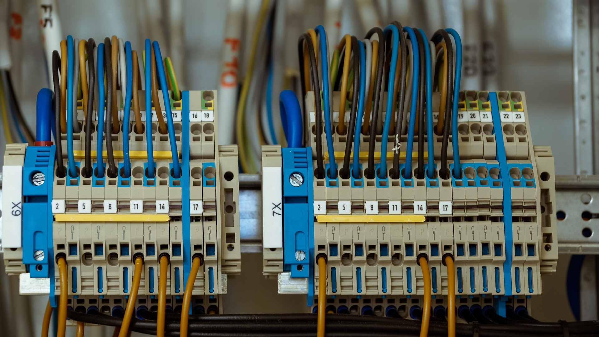
▲ 다이오드를 이용한 대책은 그라운드 경로를 만들어
바이패스 되는 경로를 많이 형성해주는 것이다
ESD 대책
VCC는 가장 일반적으로 적용되는 방식으로 Diode를 두 개중 하나는 (+)에 놓고 다른 하나를 (-)에 놓아 2개를 직렬 구성하는 방식이다. 이 방식은 양(-)극성의 정전기와 양(-)극성의 정전기에 대해 다이오드가 각각 역할을 분담하는 형태의 동작 구조를 가진다. 따라서 IC의 내부 회로의 포트에도 구성된다.
TVS(Transient Voltage Suppression)는 제너 다이오드 두 개를 마주보게 구성한 방식의 등가회로다. 순방향에서 다이오드 턴온(Turn-on) 특성을 가지며 역방향 바이어스에서 Breakdown을 일으켜 역방향으로 급격히 턴온 되는 특성을 이용한 소자다.
Varistor(Variable Resistor)는 소자 양단에 걸리는 전압 값에 따라 저항 값이 변화되는 반도체 소자의 성격을 가지며, 구성물은 ZnO(산화아연)이 주를 이루는 화합물 반도체다. 정격 전압에서는 절연체 절연 저항이 유지되나 순간 과전압 발생시 수 mΩ 이하의 도체로 저항 값이 급격하게 감소하는 특성을 가진다.
PCB 대책
ESD대책 소자는 외부 I/O Connector와 가깝게 하고 ESD소자의 Trace(PCB패턴)의 길이를 최소화 해야 한다. 노이즈(Surge) 발생원에서 대책하지 않으면 인접 PCB에 서지펄스가 넘어갈 우려가 있다.
따라서 노이즈(Surge)를 흡수할 접지 패턴이 불안하면 아무런 효과를 볼 수 없기 때문에 ESD대책 부품을 많이 사용하는 것이 중요하지 않다.
ESD소자의 접지선 처리는 Chassis나 Power 접지에 연결해야 하며 신호접지에 연결하면 순간적인 서지전압에 의한 신호접지 흔들림이 우려된다. 불가피하게 Chassis나 Power접지가 없거나 회로적 연결이 불가할 경우에는 신호의 면적이 넓은 영역에 굵고 짧게 PCB패턴을 처리해야 한다.
커패시턴스는 뾰족하게 설계하면 ESD가 머물 수 있어 터진다. 터지면 라인이 망가지기 때문에 45도 설계를 한다. 90도 설계하는 EMI 노이즈는 많이 방사가 되기 때문이다.
또한, 그라운드 설정의 경우 모서리부분에 설계를 해야한다. 이때 라운드 형태로 설계해서 ESD 영향을 최소화해야 한다.
Ethernet 기기 layout
Ethernet 기기를 터놓는 이유는 ESD가 들어오면 전하가 돈다. 돌면서 마그네틱 필드를 유발하는데 그 루프안테나 현상으로 문제가 될 수 있다. 그래서 뚫어서 경로를 차단해야 한다. 그러면 Monting Hole을 통해 그라운드 쪽으로 빠져나갈 수 있다. 이외에도 커패시터를 통해 밖으로 나갈 수 있도록 대책이 세워져 있다.
스위칭 회로에서의 유도 전류와 유도 기전력
유도 기전력은 스위칭에 의한 스파크 현상을 의미한다. 처음 초기 닫으면 역방향으로 에너지가 발생한다. 이런 현상은 에너지를 갖고 있지 않기 때문에 유도 기전력으로 나타나게 된다.
일정 시간 이후 스위치를 열면 지속적으로 에너지를 저장하고 있다가 순간적으로 전류를 뽑아낸다. 전류를 뽑으며 경로가 없어 뒤로 가면 커다랗게 유도전압이 발생한다. 인덕턴스가 클수록 더 효과는 강력하게 나타난다.
따라서 이런 현상을 방어해야 하는데 이때 대책을 위한 회로가 snubber 회로다. 사람이 할 수 없는 고전압을 on-off 해주는 계전기의 경우 이런 일이 많이 발생하는데 계전기 자체가 인덕턴스를 많이 가지고 있다.
모델링을 해보면 전류가 닫으면 쭉 가고 에너지를 저장한다. 스위치를 여는 순간 저장한 에너지 나타나며 뒤로 뺀다. 그렇게 순간적으로 전압을 만들어 낸다. 이 문제는 커다란 전압이다 보니 문제가 생긴다. 그래서 지속적으로 반복되면 시스템이 대미지를 입는다.
따라서 다이오드를 사용해 snubber 회로가 있는 경우 나머지 전류는 다이오드 내에서 흡수할 수 있는 대책을 세워줘야 한다.
이때 다이오드를 쓸 수도 있고 저항이나 커패시터 사용할 수 있다. 추가로 시간 변화에 따른 전압이나 전류로 나타내는데 주파수로 생각할 때 주파수 통과특성을 가진 커패시터를 저항값에서 소비해준다.
순간적인 짧은 펄스성 전압들은 주파수도면으로 보면 노이즈라고 생각하면 된다. 그래서 snubber 회로를 장착한다.
다이오드를 이용한 정전기 대책은 다이오드 물성을 이용해 TVS다이오드 Varistor 등을 사용한 대처나 바이패스 시키는 것이다. 노하우가 많이 필요해 다각적으로 연구가 필요하단 단점이 있지만 그라운드 경로를 만들어 바이패스 되는 경로를 많이 형성해줘야 한다.
정전기로도 전자 부품, 반도체, 제품 등이 쉽게 손상되고 언제든 화학물질의 폭발로 이어져 재난이 일어날 수 있다. 따라서 정전기에 대해 이해하고 더 알며 조심해야 한다.