[ Basics ] Arduino Practice - Controlling LED with Switch
주피터 · 2019-10-23 · 5
Controlling LED with a Switch
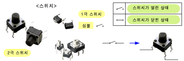
① Switch Component Description
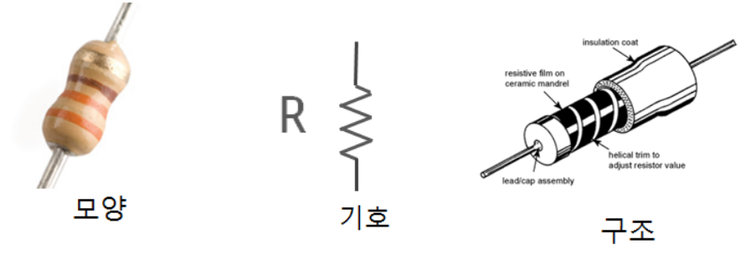
② Resistor
To limit the flow of current, you can use an electronic component called a resistor or resistance for short.
In English, it is called a resistor. A resistor is a component made to make it difficult for current to flow by using various materials and manufacturing methods.
A typical example is a resistor made by coating a thin carbon film that allows current to flow on an insulator, then carving spiral grooves to greatly extend the path through which current passes, making it difficult for current to pass through. This is called a carbon film resistor.
(Pointing to the resistor symbol on the screen) The symbol representing a resistor has a zigzag pattern like this to give the impression that current flows with difficulty, making it easy to recognize it as a resistor.
When voltage is applied to a resistor and current flows, the voltage drops at the point passing through the resistor. This is because the current has to work hard to overcome the strong resistance of the resistor and pass through. This phenomenon is called the 'voltage drop effect'.
Now let's learn how to distinguish the size of a resistor.
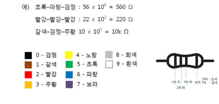
Since resistors are quite small in size and have no straight-line shape, it is difficult to write on them, so color bands are used to indicate the resistance value. Color bands are displayed using nine different colors from 0 to 9, where the first and second colors represent the resistance value, and the third represents the digit multiplier. Slightly apart from the third color band, there is a gold or silver band, which indicates the tolerance range.
For example, green-blue-black represents 56 with the digit multiplier raised by 0, meaning it is not raised, so it represents 56 ohms.
③ Breadboard
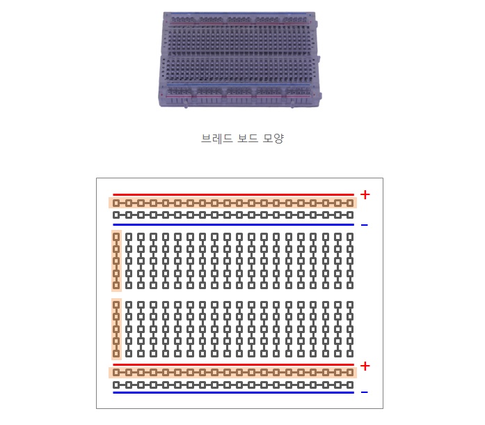
A breadboard is a board with many holes in a grid pattern, and internally these holes are connected to each other as shown in the diagram, allowing electronic components to be easily connected without soldering, and can be moved and plugged in again if connected incorrectly.
In the middle, five holes are connected vertically for easy insertion of electronic components, and in the upper and lower portions, all holes are connected horizontally for easy power supply to multiple electronic components, arranged respectively for +power supply and -power supply.
- A board for easily inserting and moving electronic components and wires to construct and test electronic circuits
- Has holes in a grid pattern where electronic components can be inserted, with internal groupings connected
- Where marked with (+) is mainly connected to power supply (5V)
- Where marked with (-) is mainly connected to ground (GROUND: 0V)
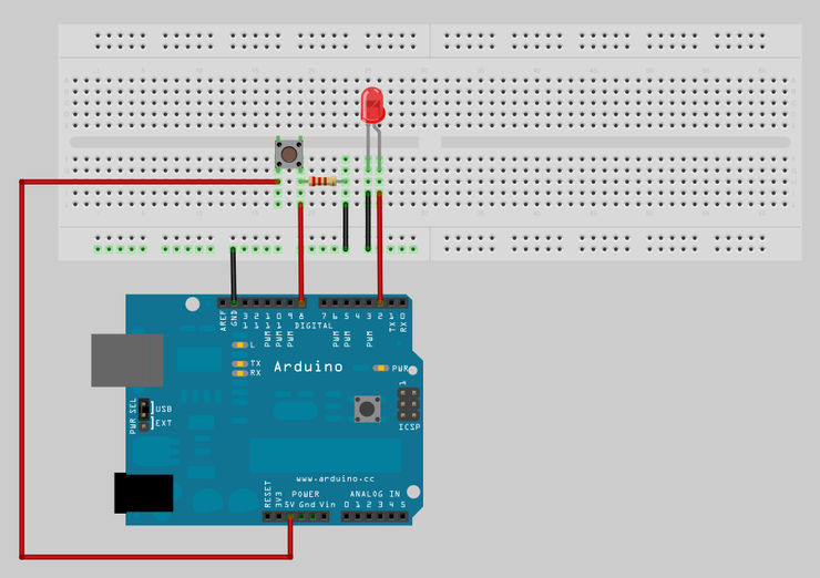
④ Hardware Configuration
Configure the hardware as shown in the diagram below.
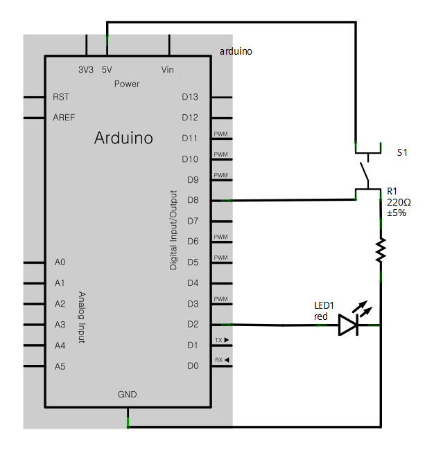
Below is the logic circuit.
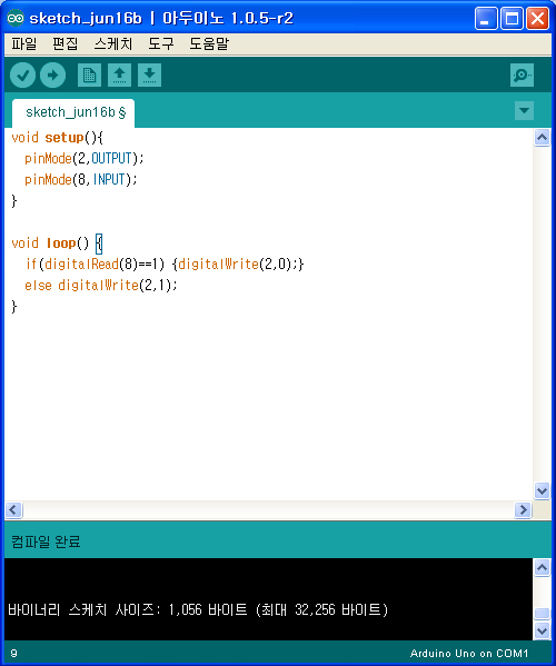
⑥ Arduino Programming
Implement the program logic.
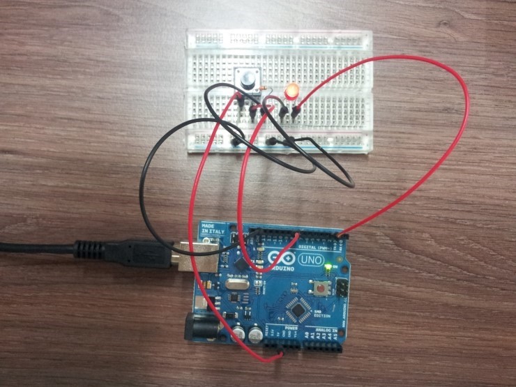
⑦ Actual Photographs
These are actual photographs of the system operating in real-time integration. Configure the board as shown below and verify the results.
5
댓글 0개
등록된 댓글이 없습니다.