

[기초] 아두이노 - 디지털 피아노 만들기
마이크로 스위치를 활용한 디지털피아노 만들기
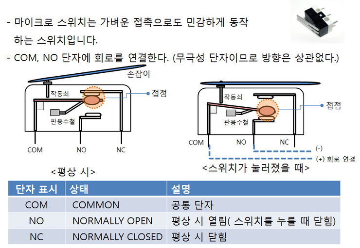
ⓞ 스위치 모양, 기호, 내부 구성 설명 그림
피아노 건반으로는 마이크로 스위치를 사용 합니다. 마이크로 스위치는 가벼운 접촉만으로도 민감하게 동작하는 스위치입니다.
마이크로 스위치는 COM, NO, NC 단자 세 개인데 COM은 회로가 열릴 때나 닫힐 때나 공통으로 사용하는 단자이고 NC은 평상시에 닫혀 있는 단자 NO는 스위치를 눌렀을 때 닫혀서 전류가 흐르게 되는 단자입니다. 그래서 평상시에는 접점이 NC 단자에 연결되어 있다가 손잡이를 누르면 NO단자에 연결이 됩니다.
그림에서 보는 것처럼 COM과 NO단자에 회로를 연결하게 되는데 NO 단자에 그라운드를 연결하면 스위치를 눌렀을 때 0 즉 FALSE값을 반환하게 됩니다.
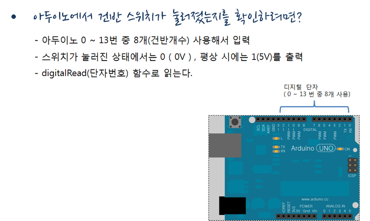
ⓞ 디지털 입력단자가 표시되어 있는 아두이노 보드
아두이노에는 디지털 단자가 0 ~ 13번까지 14개의 단자가 있는데 단자 중 8개, 즉, 건반 갯수 만큼 사용하면 됩니다. 디지털 단자에서 입력 값을 읽으려면 스케치에서는 digitalRead()함수를 호출해 사용하면 되고 인자로는 단자번호를 써 주면 됩니다. NO단자가 그라운드에 연결되어 있으므로스위치가 눌러지면 0(0v)를 출력하게 됩니다.
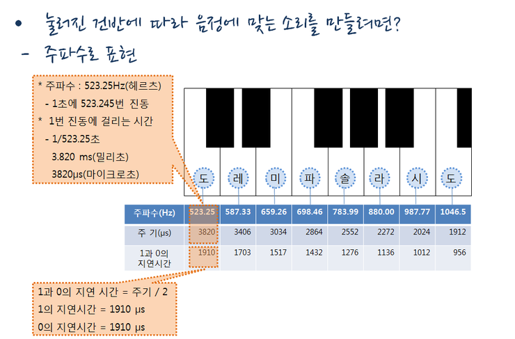
ⓞ 스위치 모양, 기호, 내부 구성 설명 그림
소리의 높고 낮음은 주파수로 표현 하는데, 높은 ‘도’음을 예로 들면, 주파수는 523.25Hz(헤르츠)입니다. 이 말은 1초에 523.25번 진동한다는 의미입니다. 그러므로 한번 진동하는데 걸리는 시간은 1/523.5초, 3.820ms(밀리초), 3820μs(마이크로초)입니다.
그래서 3820μs라는 짧은 시간동안 1과 0이 한 번 반복되는데,1과 0의 지연시간은 주기를 반으로 나눈 값입니다. 1910μs동안 1을, 1910μs 동안 0을 번갈아가면서 반복하여 출력하면, 높은 ‘도’에 해당하는 523.25Hz의 음을 만들어 낼 수 있는 것입니다. 소리의 높낮이를 주파수로 표현하는 것을 이용해 주기의 ½ 마이크로 초만큼 1과 0값을 반복해 주면 해당 음에 맞는 소리를 만들 수 있습니다.
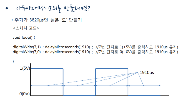
ⓞ 소리를 만드는 스케치
주기가 3820마이크로초인 높은 ‘도’를 만드는 스케치를 보면 7번 단자에 소리를 출력하기 위한 스피커가 연결되어 있다고 가정합니다. 그리고 주기가 3820마이크로초이므로 그의 절반인 1910마이크로초만큼 5V를 출력하고 또 1910마이크로초만큼 0V를 유지하면 사각파 형태의 펄스가 만들어져서 높은 ‘도’ 소리가 만들어지는 것입니다.
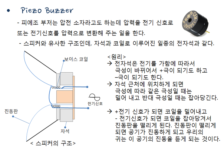
ⓞ 피에조 부저
스피커로 이용하기 위한 전자부품으로는 피에조 부저를 이용해 보겠습니다. 피에조 부저는 압전 소자라고도 하는데 압력을 전기 신호로 또는 전기신호를 압력으로 변환해 주는 일을 합니다.
마이크나 스피커와 유사한 구조인데, 스피커는 자석과 코일로 이루어진 일종의 전자석과 같습니다.
그 원리를 한번 살펴보면, 전자석은 전기를 가함에 따라서 극성이 바뀌어서 +극이 되기도 하고 ?극성이 되기도 합니다. 자석 근처에 위치하게 되면 극성에 따라 같은 극성일 때는 밀어 내고 반대 극성일 때는 잡아당깁니다. 그림과 같이 전기 신호가 가해진다면 어떻게 될까요 +전기 신호가 되면 코일을 밀어내고 - 전기신호가 되면 코일을 잡아당겨서 진동판을 떨리게 됩니다. 진동판이 떨리게 되면 공기가 진동하게 되고 우리의 귀는 이 공기의 진동을 듣게 되는 것입니다.
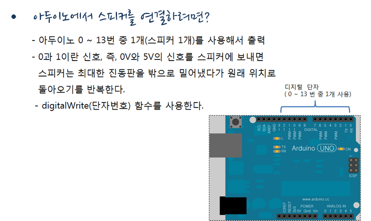
ⓞ 디지털 입력단자가 표시되어 있는 아두이노 보드
아두이노에 스피커는 아두이노 0 ~ 13번 중 1개(스피커 1개)를 사용해서 출력하면 됩니다.
아두이노 출력핀에 연결하고 0과 1이란 신호(0V와 5V)를 스피커에 보내면 스피커는 최대한 진동판을 밖으로 밀어냈다가 원래 위치로 돌아오기를 반복하게 됩니다. 스케치를 작성할 때 digitalWrite(단자번호) 함수를 사용합니다.
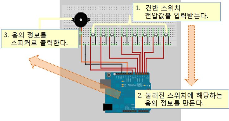
ⓞ 디지털 피아노의 동작 순서를 설명하기 위한 다이어그램
건반 스위치 8개가 연결된 디지털 단자에서 전압 값을 입력받아 옵니다. 건반이 눌러진 상태이면 1(5V)을 출력하게 되고 눌러진 건반에 해당하는 음의 주기에 따라 1과 0으로 반복되는 전자파를 스피커에 출력하여 소리를 만들어 내게 됩니다.
.png)
ⓞ 필요한 재료들의 목록
어떤 부품들이 필요한지 한 번 정리를 하면 건반으로 사용하는 마이크로 스위치 8개, 스피커로 사용하기 위한 피에조 부저 1개, 부품들을 꽂아서 회로를 만들기 위해 사용하는 브레드보드 4개, 이것처럼 소형인 경우 4개를 연결해서 사용해도 됩니다.가로 길이가 15cm 긴 경우에는 하나로 구성해도 됩니다.
그리고 부품들을 연결할 점퍼선 1 세트, 아두이노 보드 1개, 아두이노 보드와 컴퓨터를 연결할 USB 케이블 한 개, 그리고 개인용 컴퓨터가 1 세트 필요합니다.
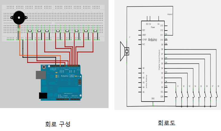
ⓞ 회로구성과 회로도
그림과 같이 회로구성대로 브레드보드 위에 부품들을 배치하고 점퍼선을 이용하여 연결을 해줍시다. 모두 연결한 뒤에는 부품의 방향과 단자 번호 등을 다시 한번 확인 해보세요.
ⓞ 스케치 순서도
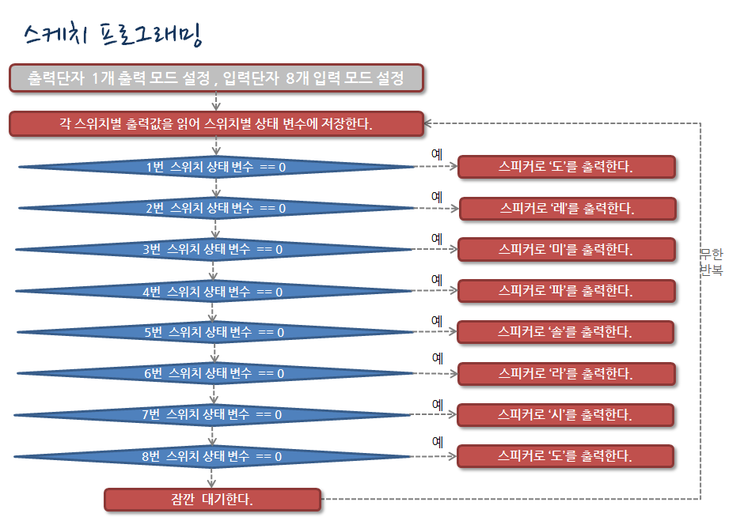
처음 setup() 함수 에서는 출력단자 1개를 출력 모드로 설정하고 입력단자 8개를 입력모드로 설정합니다. 그리고 스위치별로 출력값을 확인해서 스위치별 상태 변수에 저장합니다.
1번 스위치 상태 변수값이 0이면, ‘도’건반이 눌러진 것이므로 ‘도’를 스피커로 출력합니다.
2번 스위치 상태 변수값이 0이면, ‘레’건반이 눌러진 것이므로 ‘레’를 스피커로 출력합니다.
3번 스위치 상태 변수값이 0이면, ‘미’건반이 눌러진 것이므로 ‘미’를 스피커로 출력합니다.
4번 스위치 상태 변수값이 0이면, ‘파’건반이 눌러진 것이므로 ‘파’를 스피커로 출력합니다.
5번 스위치 상태 변수값이 0이면, ‘솔’건반이 눌러진 것이므로 ‘솔’를 스피커로 출력합니다.
6번 스위치 상태 변수값이 0이면, ‘라’건반이 눌러진 것이므로 ‘라’를 스피커로 출력합니다.
7번 스위치 상태 변수값이 0이면, ‘시’건반이 눌러진 것이므로 ‘시’를 스피커로 출력합니다.
8번 스위치 상태 변수값이 0이면, ‘높은 도’건반이 눌러진 것이므로 ‘높은 도’를 스피커로 출력합니다. 그리고, 스위치가 내보내는 가짜 신호를 제거하기 위해 잠깐 대기한다. 그리고 이 과정을 무한 반복합니다.
ⓞ 작성된 스케치
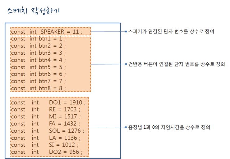
우선 상수를 미리 정의한 후 스피커가 연결된 단자를 SPEAKER란 이름으로 11번 단자를 설정했고 스위치가 연결된 단자를 btn1 ~ btn8까지의 이름으로 1번부터 8번까지 단자번호를 설정했습니다.
그리고 도,레,미,파,솔,라,시,도를 출력하기 위해 각각 ‘도’부터 ‘높은 도’까지 1과 0의 지속시간을 미리 상수값으로 정의했습니다.
ⓞ 작성된 스케치 2
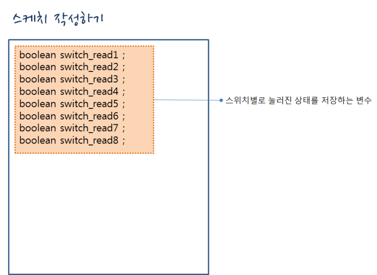
각 스위치가 눌러졌는지 상태값을 저장하기 위해 switch_button1부터 switch_button8까지 변수를 선언했습니다.
ⓞ 작성된 스케치 3
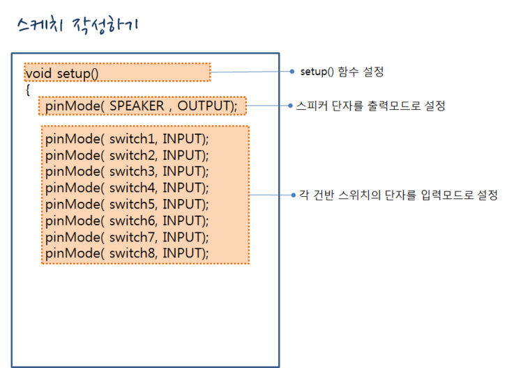
setup()함수입니다.
스피커가 연결된 SPEAKER단자를 출력모드로 설정합니다. switch1부터 switch8까지 각 스위치 단자를 입력모드로 설정합니다.
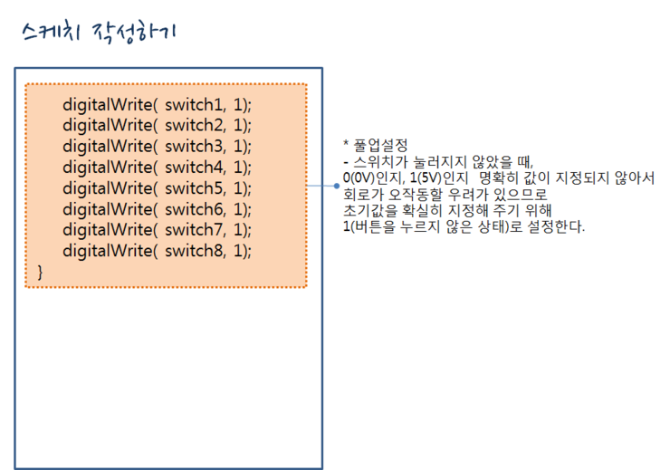
ⓞ 작성된 스케치 4
그림과 같이 하는 것을 풀업 설정을 한다고 하는데, 스위치가 눌러지지 않았을 때, 0(0V)인지, 1(5V)인지 명확히 값이 지정되지 않아서 회로가 오작동할 우려가 있으므로 초기값을 확실히 지정해 주기 위해 1로 설정하여 위치가 눌러지지 않은 상태라는 것을 확실히 합니다.
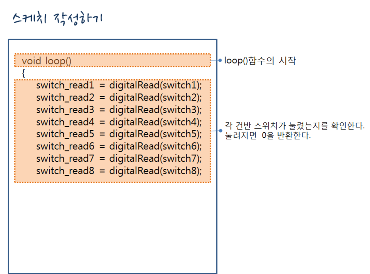
ⓞ 작성된 스케치 5
각 건반 스위치가 눌렸는지를 확인해서 Switch_read1부터 switch_read8까지 변수에 값을 저장합니다. 스위치가 눌러지면 0이 저장됩니다.
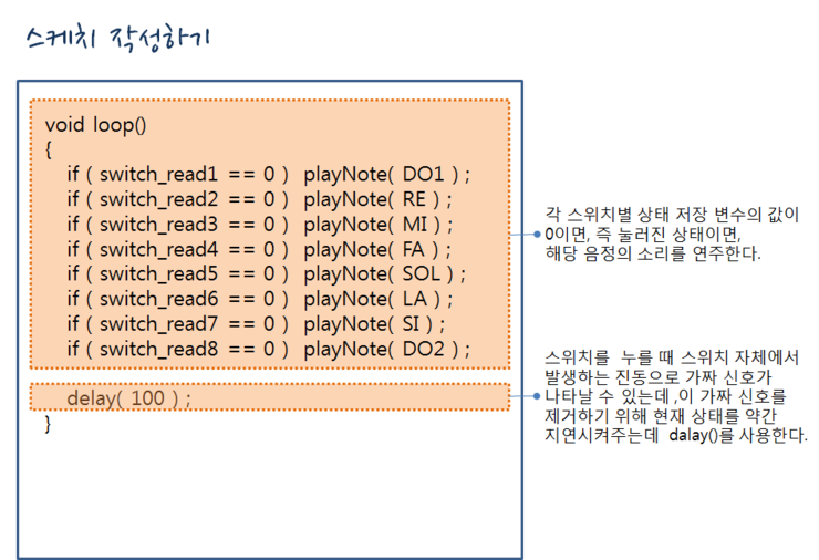
ⓞ 작성된 스케치 6
각 스위치별 상태 저장 변수의 값을 읽어 그 값이 0이면 스위치가 눌러진 상태이므로 해당 음정의 소리를 연주합니다.그리고, 스위치를 누를 때 스위치 자체에서 발생하는 진동으로 가짜 신호가 나타날 수 있는데 ,이 가짜 신호를 제거하기 위해 현재 상태를 약간 지연시켜주는데 dalay(100)를 사용해 100마이크로초 정도를 대기하고 전체 과정을 다시 무한반복 합니다.
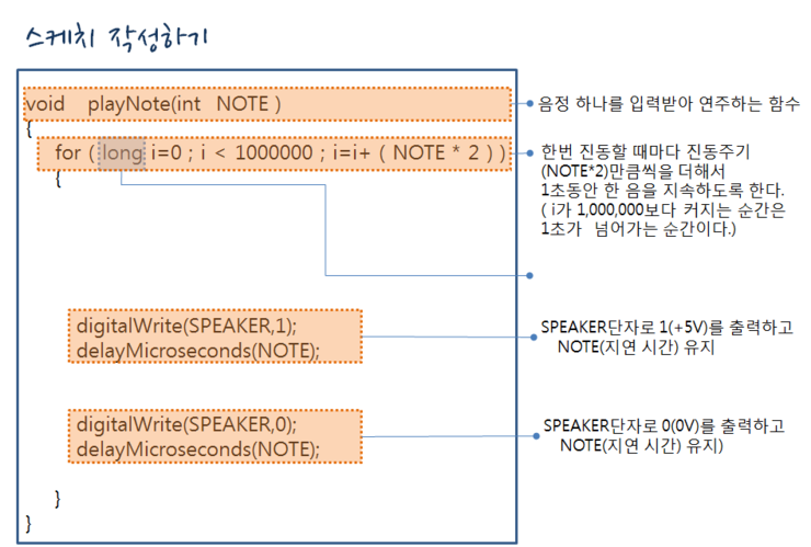
ⓞ 작성된 스케치 7
playNote()라는 함수를 별도로 작성했는데요. 인자로 NOTE라고 하는 변수에 어떤 음을 연주할 것이지 해당 음의 지연시간값을 입력받아 그 지연시간 만큼 1과 0을 스피커에 반복 출력해 줍니다. For문에서 한번 진동할 때마다 진동주기 (NOTE*2)만큼씩을 더해서 1초동안 한 음을 지속하도록 했는데 i가 1,000,000보다 커지는 순간이 1초가 넘어가는 순간이 됩니다.
그리고 i를 long 타입으로 지정했습니다. integer는 -32,768 ~ 32,767 까지의 숫자만 담을 수 있으므로 1,000,000를 담기에는 너무 작으므로 long타입을 사용 합니다. 그래서 SPEAKER 단자로 1(5v)를 출력하고 NOTE만큼 지연 시간을 유지하고 SPEAKER 단자로 0(0v)를 출력하고 NOTE만큼 지연 시간을 유지하기를 1초 동안 반복합니다.
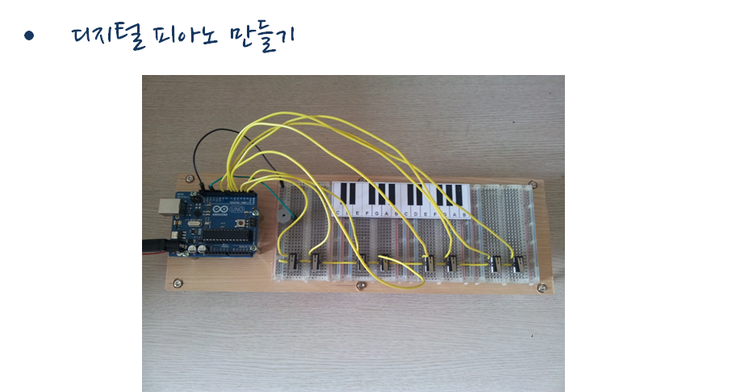
ⓞ 완성된 사진
< 오류사례 >
회로를 다 연결 했는데도 잘 안 되는 경우가 있습니다. 소리가 나지 않을 때는 피에조 부저를 제대로 연결했는지 확인해 보세요. 긴 다리를 +에 연결합니다.
건반을 누르지도 않았는데 아무렇게나 소리가 나면 않을 경우에는 풀업이 제대로 설정이 되지 않았기 때문입니다. 건반을 누르지 않은 상태에서는 입력되는 값이 0인지 1인지 확실히 지정되지 않아 오작동하는 경우가 생기는데 입력모드를 설정하고 나서 초기 출력값을 1(건반을 누르지 않은 상태)로 설정했는지 확인합니다.