

[기초] 아두이노 - 모터 제어 선풍기 만들기
자연바람 선풍기 만들기
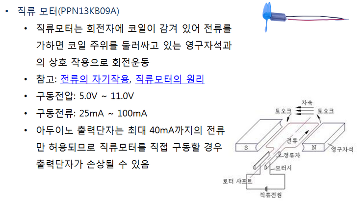
ⓞ직류 모터의 외관, 내부 구조 이미지
선풍기 날개를 회전시키기 위해서는 직류 모터를 사용하는 것이 좋습니다. 직류 모터는 회전자에 코일이 감겨 있어 전류를 가하면 자기장이 발생하여 코일 주위를 둘러싸고 있는 영구자석과의 상호작용으로 회전 운동을 합니다.
회전자가 반바퀴를 회전하면 회전자에서 발생하는 자기장의 방향이 반대를 향하게 되어 방향을 바꿔줘야 하므로 브러시를 이용하여 직류전원의 극성이 반대로 공급되도록 합니다. 직류 모터는 공급되는 전압에 따라 회전속도를 쉽게 조절할 수 있고, 회전력이 강하기 때문에 여러 가지 용도로 사용이 됩니다. PPN13KB09A 직류 모터는 5V의 작은 전압으로도 회전시킬 수 있는 작은 직류 모터입니다. 최소한 25mA ~ 100mA 정도의 전류를 흐르게 해줘야 동작을 시킬 수 있습니다.
하지만 아두이노의 출력단자는 최대 40mA 까지 밖에는 흐르게 할 수 없습니다. 더 많은 전류가 흐르도록 회로를 연결하면 아두이노 내부의 부품들이 망가질 수 있습니다.
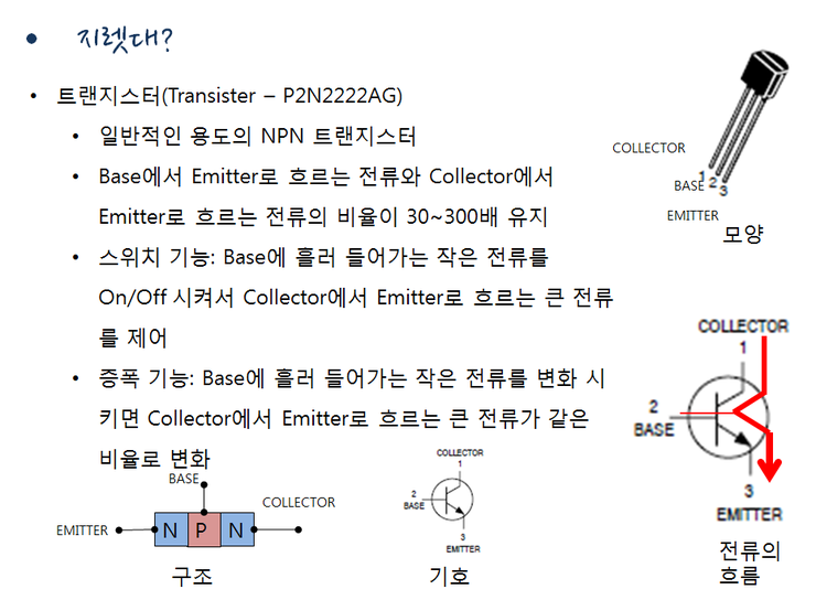
ⓞ 트랜지스터 모양, 기호, 내부 구성 설명 그림
아두이노의 출력단자와 모터 사이에 지렛대 같은게 하는데 아두이노의 출력단자에서는 작은 전류만 흘러 나오도록 하고, 모터에는 별도의 큰 전류가 흐르게 한 다음에 아두이노의 출력단자의 전류 변화에 비례해서 모터에 흐르는 큰 전류가 변화할 수 있도록하는 지렛대 같은 전자 부품이 있어야 합니다. 그런 지렛대 같은 역할을 해줄 수 있는 전자 부품이 바로 트랜지스터 입니다.
트랜지스터는 다리가 두개인 다이오드와 비슷하지만, 다리가 하나 더 있어서 세 개의 다리를 가지고 있습니다. 세개의 다리는 각각 에미터, 베이스, 그리고 컬렉터라고 부릅니다.
우리가 사용하려는 P2N2222AG 트랜지스터는 일반적인 용도로 사용되는 트랜지스터인데, 베이스에서 에미터로 흐르는 전류와 컬렉터에서 에미터로 흐르는 전류의 비율이 100배 정도를 유지하는 성질을 가지고 있습니다. 베이스에 1mA의 전류를 흘려 보내고, 컬렉터에 100mA의 전류를 흘려 보내면 에미터에서는 두 전류의 합에 해당하는 101mA의 전류가 흐르게 됩니다.
트랜지스터는 크게 두 가지 용도로 사용할 수 있는데, 첫번째는 스위치 기능입니다. 베이스에서 에미터로 흐르는 전류을 차단 시키면 콜렉터에서 에미터로 흐르는 전류도 흐르지 않게 되고, 베이스에서 에미터로 흐르는 전류를 흐르게 해주면 콜렉터에서 에미터로 흐르는 전류도 흐르기 시작합니다. 두번째는 증폭 기능입니다. 베이스에서 에미터로 흐르는 작은 전류을 변화 시키면 콜렉터에서 에미터로 흐르는 큰 전류도 같은 비율로 변화합니다. 예를 들어 증폭률이 100배라고하면, 베이스에서 에미터로 흐르는 전류를 1mA에서 2mA로 증가시키면, 콜렉터에서 에미터로 흐르는 전류는 100mA에서 200mA로 증가하게 됩니다.

ⓞ 트랜지스터 사양
컬렉터에 모터를 연결하고 더불어서 P2N2222AG 트랜지스터의 컬렉터-에미터 사이의 최대 전압은 40V, 컬렉터에 흐를 수 있는 최대 전류는 600mA나 되므로 컬렉터에 직류 모터를 연결해도 충분히 견딜 수 있습니다. 아두이노의 출력단자를 베이스에 연결하고 아두이노의 출력단자에서는 최대 5볼트가 출력되는데, 트랜지스터의 베이스-에미터 사이의 최대전압도 6V이므로 안전합니다.
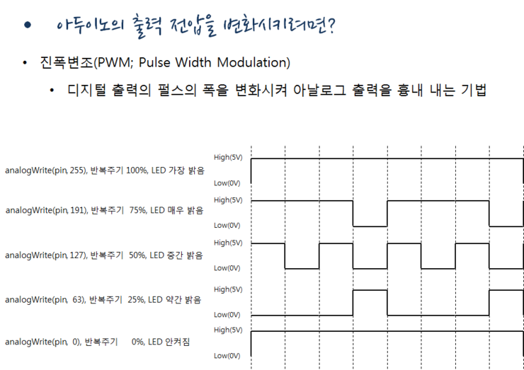
ⓞ 진폭변조 PWM
직류 모터의 속도를 조절하려면 아두이노의 출력 단자에서 나오는 전압을 0 볼트나, 5 볼트가 아닌 그 사이의 전압이 출력되도록 해야 합니다. 아두이노의 출력 단자는 0V 와 5V 이외의 다른 임의의 전압을 출력할 수 있는 방법이 없습니다. 하지만 “진폭변조” 라고 하는 방법을 사용하면 비슷한 효과를 내게 할 수 있습니다. 진폭 변조 기법은 0V와 5V를 빠르게 반복 출력하여, 출력단자에 연결된 부품에 전달되는 전류의 총량을 조절하여 중간의 전압을 출력한 것과 같은 효과를 얻는 방법입니다.
예를 들어, 2.5V의 출력이 필요하다면, 같은 시간 간격으로 0V와 5V를 번갈아 출력합니다.
그러면 큰 시간간격에서 보았을 때는 2.5V로 연속적으로 전류가 흘러나온 것과 동일한 양의 전류가 흘러나오게 되므로 같은 효과를 얻을 수 있습니다. 5V의 75%에 해당하는 3.75V의 출력이 필요하다면, 5V를 3회 출력한 후 0V를 1회 출력하는 것을 빠르게 반복하면 됩니다.
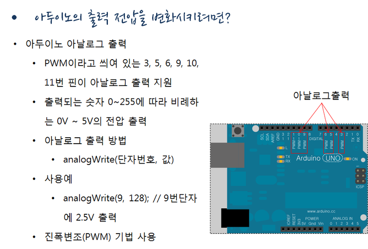
ⓞ 아두이노 PWM 출력 단자
아두이노의 모든 디지털 입출력 단자에 PWM 기법을 사용할 수 있는 것은 아니고 아두이노 보드는 14개의 디지털 입출력 단자 중에 PWM이라고 씌여 있는 3, 5, 6, 9, 10, 11번 6개의 단자만 PWM 출력을 지원합니다.
스케치에서 아날로그 출력을 하기 위해서는 analogWrite(출력단자번호, 값) 함수를 호출하면 됩니다. 값은 0 ~ 255 를 줄 수 있고, 값에 따라 0V ~ 5V를 출력됩니다.
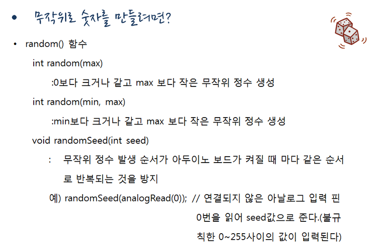
ⓞ random() 함수
random() 함수를 호출하면 임의의 무작위 값을 발생시킬 수 있습니다. 괄호 안에 최대값을 주면, 0보다 크거나 같고 최대값보다 작은 무작위 정수를 생성합니다. 괄호 안에 최소, 최대값을 주면, 최소 값보다 크거나 같고 최대 값보다 작은 무작위 정수를 생성합니다. 하지만 약간의 문제점이 있습니다. random() 함수를 호출할 때 마다 무작위의 값을 생성해내기는 하지만 100% 완전한 무작위 값은 아닌 것이, 스케치 프로그램이 다시 시작되면 즉, 아두이노 보드의 전원이 다시 공급되면 그 이전과 동일한 순서로 무작위 값이 생성된다는 것입니다. 그래서 무작위 값의 시작 기준점을 매번 다르게 설정을 해줄 필요합니다.
그 시작 기준점을 randomSeed() 함수에 씨앗 값을 인자로 주어 지정할 수 있습니다. 씨앗 값을 매번 다르게 주기 위해서는 analogRead(단자번호)함수를 이용합니다. 아무 곳에도 연결되지 않은 입력 단자는 불안정한 상태이기 때문에 analogRead()함수로 읽으면 그 때 그 때 0 ~ 255 사이의 임의의 값이 읽히게 됩니다. 이 값을 씨앗 값으로 이용합니다.
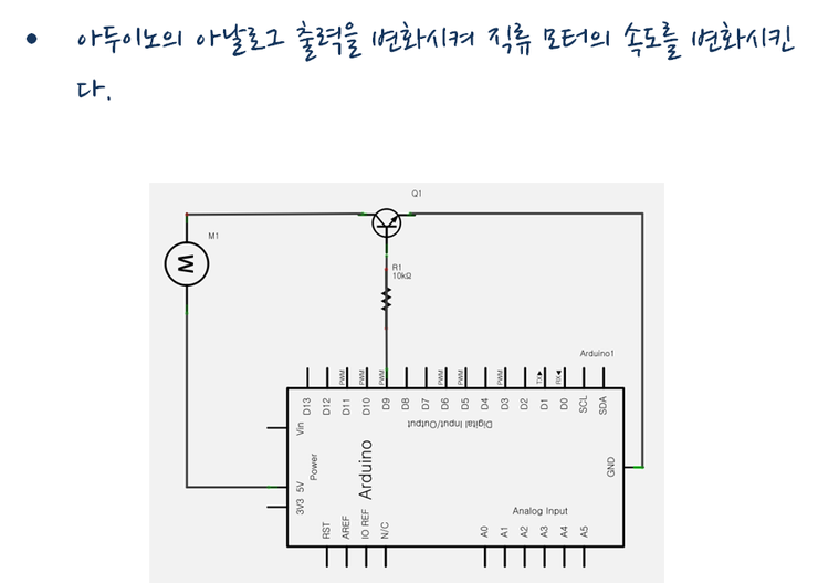
ⓞ 아두이노에 저항과 트랜지스터, 모터를 연결한 회로
아두이노의 9번 단자에 저항을 연결하고, 거기에 트랜지스터의 베이스를 연결합니다.
저항은 아두이노 출력 단자의 전류를 40mA 이내로 제한하고, 트랜지스터에 흘러 들어가는 전류도 제한 하기 위한 것입니다. 트랜지스터의 에미터는 접지(0V)에 연결하고 직류모터를 컬렉터에 연결합니다. 직류 모터의 다른 쪽은 5V 전원에 연결 합니다. PWM이 지원되는 6개 단자 중의 하나를 연결하여야 합니다.
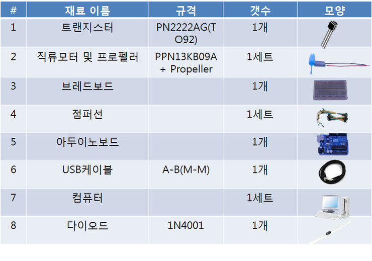
ⓞ 부품들의 목록
부품들을 준비해야 되는지 한번 정리하면 우선 트랜지스터가 1개, 직류모터와 프로펠러 각각 1개씩, 부품들을 꽃을 브레드 보드 1개, 부품들을 연결할 점퍼선 1 세트, 아두이노 보드 1개, 아두이노 보드와 컴퓨터를 연결할 USB 케이블 한 개, 그리고 개인용 컴퓨터가 1 세트 필요합니다.
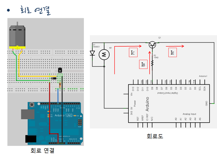
ⓞ 회로구성과 회로도
회로 구성대로 브레드보드 위에 부품들을 배치하고 점퍼선을 이용하여 연결을 해줍시다. 모두 연결한 뒤에는 부품의 방향과 다리 순서 등을 다시 한번 확인 합니다.
ⓞ 회로구성과 회로도
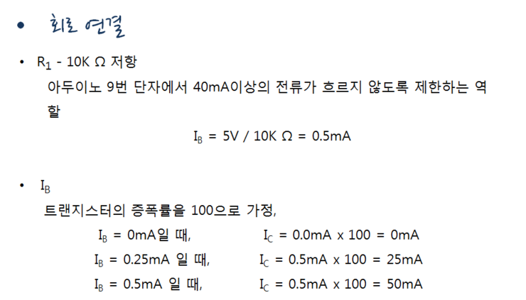
저항 R1은 10 킬로오옴을 사용했는데, 아두이노 출력단자는 최대 5V의 출력이 나올 수 있습니다. 오옴의 법칙에 따라 5볼트 나누기 10 킬로오옴해보면, 트랜지스터의 베이스애 흐르는 전류는 최대 0.5mA가 흐르게 됩니다. 0.5mA는 아두이노 출력단자의 최대 허용 전류인 40mA보다 훨씬 작기 때문에 아두이노를 망가뜨릴 염려가 없습니다. 또한 트랜지스터의 증폭률을100으로 가정하면, 모터에는 0.5 밀리암페어의 100배인 최대 50mA가 흐르게 되므로 모터도 안전하게 됩니다.
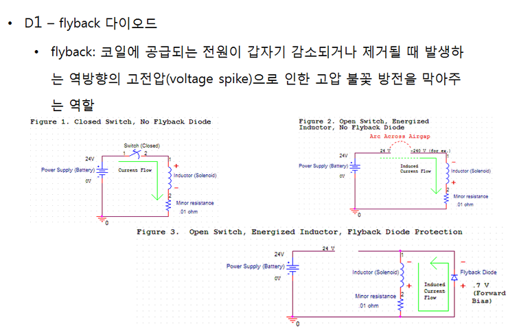
ⓞ 플라이 백 다이오드의 역할 설명
회로도의 모터 옆을 보면 계획에는 없었던 다이오드가 하나 사용된 것을 볼 수 있는데, 이 다이오드를 플라이백 다이오드라고 부릅니다. 직류 모터의 내부에는 전자석 역할을 하는 코일이 들어 있고, 이 코일이 반 바퀴 회전할 때 마다, 브러시 접점이 반대로 연결되면서 코일의 자기장을 반대로 바꾸어 주게 됩니다.
그런데, 브러시의 접접이 반대로 연결되는 순간 즉, 코일이의 전원 공급이 끊어지는 순간에, 코일에 형성되어 있던 자기장이, 전압이 갑자기 낮아지는 것에 저항하여 커다란 역 전압을 발생시키는 현상이 발생하게 됩니다. 이 역전압에 의해 브러시 접점에 불꽃이 튀게 되고, 이 때문에 모터가 망가지거나 화재가 발생할 수 있습니다. 그래서, 이 역전압에 의한 전류를 플라이백 다이오드로 비껴 흐르게 함으로써 모터를 보호하는 역할을 하게 합니다.
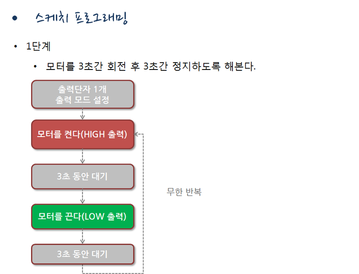
ⓞ 스케치 순서도
처음 setup() 함수 에서는 출력단자 한 개를 출력 모드로 설정을 한 후 loop() 함수에서는 맨 처음 모터를 켠다. 그다음 3 초간 대기후, 모터를 끈다 다시 3초간 대기 한다. 이 과정을 무한 반복합니다.
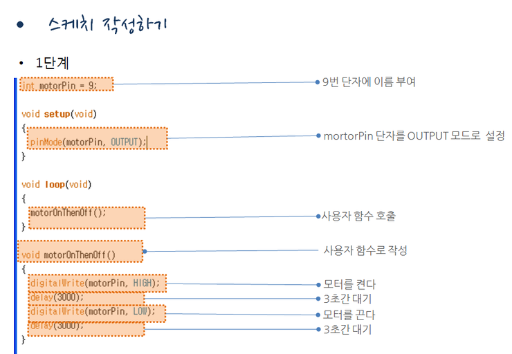
ⓞ 작성된 스케치
우선 9번 단자를 사용하기 위해 정수형 변수 motorPin을 선언해서 9를 대입했습니다.
setup() 함수에서는 pinMode함수를 호출하여 motorPin 단자를 출력으로 설정하였습니다.
그 다음 loop()함수에서는 motorOnThenOff()함수를 호출하였습니다. motorOnThenOff()함수는 스케치에 내장된 함수가 아니고, 사용자 함수입니다. 즉, 우리가 직접 함수를 작성해야 합니다.
motorOnThenOff() 함수에서는 digitalWrite()함수를 호출하여 모터를 켜고, delay()함수를 호출하여 3 초간 대기 후 다시 digitalWrite() 함수를 호출하여 모터를 끄고, delay() 함수를 호출하여 3 초간 대기 하도록 합니다. 작성된 스케치를 아두이노에 업로드하고 모터가 3 초 동안 회전하다가 3초 동안 꺼지는 동작을 반복하는지 확인해 봅시다.
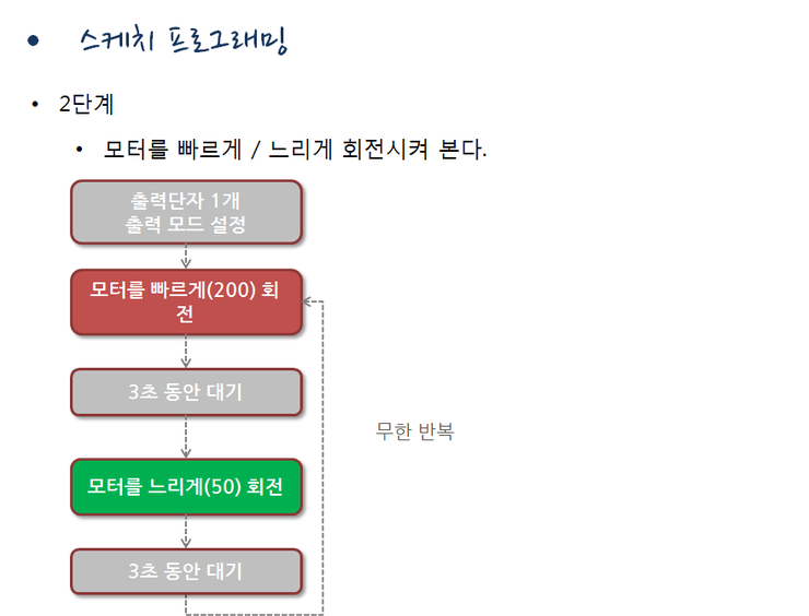
ⓞ 스케치 순서도
처음 setup() 함수 에서는 출력단자 1 개를 출력 모드로 설정을 한 후 loop() 함수에서는 맨 처음 모터를 빠르게(200) 회전시킨다. 그 다음 3 초간 대기후, 모터를 느리게(50) 회전시킨다. 다시 3초간 대기 한다. 이 과정을 무한 반복한다.
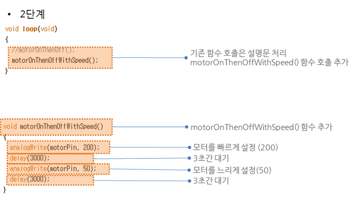
ⓞ 작성된 스케치 스크린샷
loop()함수에서는 motorOnThenOff()함수는 설명문 처리를 해주었고, motorOnThenOffWithSpeed()함수를 새롭게 호출 했습니다. morotOnThenOffWithSpeed() 함수에서는 analogWrite()함수를 호출하여 모터를 빠르게 돌리고, delay()함수를 호출하여 3 초간 대기 후 다시 analogWrite() 함수를 호출하여 모터를 느리게 돌리고, delay() 함수를 호출하여 3 초간 대기 하도록 합니다. 작성된 스케치를 아두이노에 업로드하고 모터가 3 초 동안 빠르게 회전하다가 3초 동안 느리게 회전하는 동작을 반복하는지 확인해 봅시다.
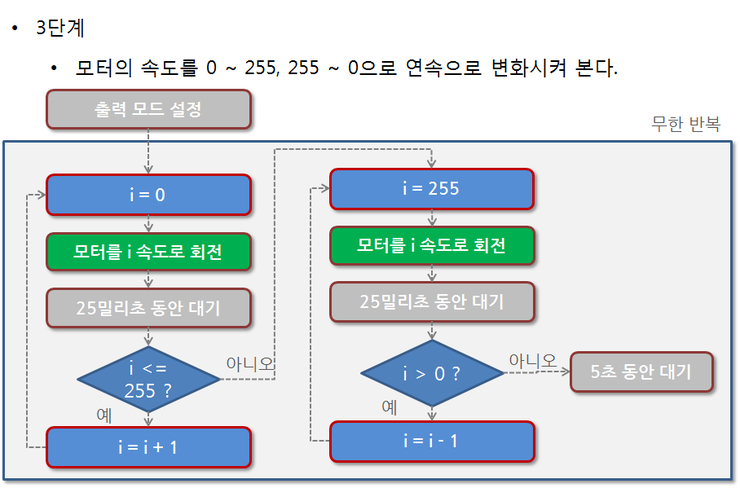
ⓞ 스케치 순서도
처음 setup() 함수 에서는 출력단자 하나를 출력 모드로 설정을 한 후 loop() 함수에서는
맨 처음 반복문에서는 i 값을 0에서 255까지 1씩 증가하도록 하고, 모터의 속도를 i 값의 속도로 회전, 25밀리초 대기를 반복하도록 합니다. 두 번째 반복문에서는 i 값을 255에서 0까지 1씩 감소하도록 하고, 모터의 속도를 i 값의 속도로 회전, 25밀리초 대기를 반복하도록 합니다. 5초간 대기 한다. 이 과정을 무한 반복한다.
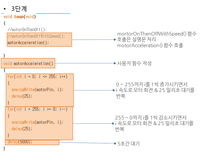
ⓞ 작성된 스케치
setup() 함수는 수정 부분이 없습니다. 그 다음 loop()함수에서는 motorOnThenOffWithSpeed()함수 호출은 설명문 처리를 하고 motorAceleration()함수를 호출합니다.
loop() 함수 및에 motorAcceleration() 함수를 추가하고, 맨 처음 반복문에서는 i 값을 0에서 255까지 1씩 증가하도록 하고, analogWrite() 함수를 i 값을 주어 호출하고, 25밀리초 대기를 반복하도록 합니다. 두 번째 반복문에서는 i 값을 255에서 0까지 1씩 감소하도록 하고, analogWirte() 함수를 i 값을 주어 호출하고, 25밀리초 대기를 반복하도록 합니다. 그리고 난 후 5초간 대기하도록 합니다. 이 과정을 무한 반복합니다.
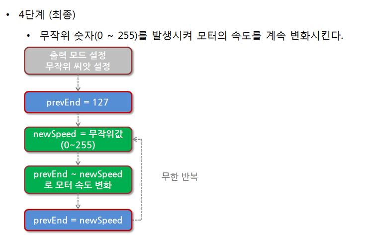
ⓞ 스케치 순서도
setup() 함수에는, 출력모드를 설정하고, 무작위 씨앗 값을 지정합니다. 또 prevEnd 변수를 선언하여 초기값을 중간 값인 127로 지정합니다. loop() 함수에서는 newSpeed 변수에 무작위 값을 생성하여 대입하고, prevEnd ~ newSpeed 까지 모터 속도를 변화시킵니다. 마지막에는 prevEnd 변수에 newSpeed값을 대입하고 다시 처음으로 되돌아 갑니다.
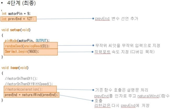
ⓞ 스케치 스크린샷 1
직전의 모터속도를 저장해두기 위한 정수형 변수 prevEnd 를 선언합니다. 그다음 setup() 함수에서는 randomSeed() 함수를 호출하면서 씨앗 값으로는 아무 것도 연결되어 있지 않은 0번 입력 단자를 analogRead()함수로 읽어 지정했습니다. 디버깅을 위해서 직렬 포트의 속도도 9600 보오로 지정해주었습니다. 그 다음 loop()함수에서는 우선, motorAcceleration() 함수 호출은 설명문 처리를 해주었고 naturalWind()함수를 호출하면서 인자로 prevEnd 값을 줍니다. 호출된 결과는 다시 prevEnd 변수에 대입합니다.
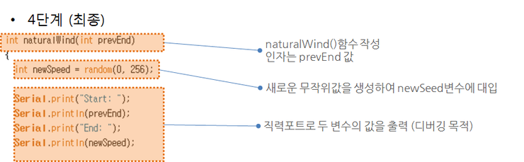
ⓞ 스케치 스크린샷 2
naturalWind 함수는 prevEnd 값을 받아야 하니까 정수값을 prevEnd에 받고, 다시 정수값을 돌려주어야 합니다. 우선 정수형 변수 newSpeed를 선언하고 무작위값을 생성하여 대입합니다. 디버깅을 위해서 직렬포트로 prevEnd값과 newSpeed값을 출력합니다.
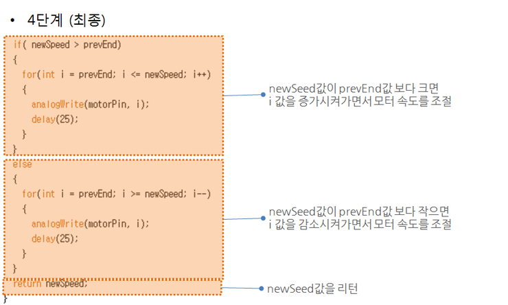
ⓞ 스케치 스크린샷 3
newSpeed 값이 prevEnd 값보다 크면, 반복문을 i가 prevEnd 에서 시작해서 newSpeed가 될 때 까지 1씩 증가시키면서 반복시킵니다. 반복문 내에서는 analogWrite()함수를 i값을 출력하도록 호출하고, delay()를 25 밀리초하도록 합니다. newSpeed 값이 prevEnd 값보다 작다면 시작값과 종료값을 반대로 해주면 됩니다. 마지막에는 newSpeed 변수의 값을 리턴합니다.
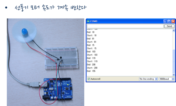
ⓞ 완성된 사진
이제 모터의 속도가 계속 불규칙하게 변화하는 모습을 볼 수 있습니다. 시리얼 모니터에서는 시작 속도와 종료 속도를 볼 수 있습니다.
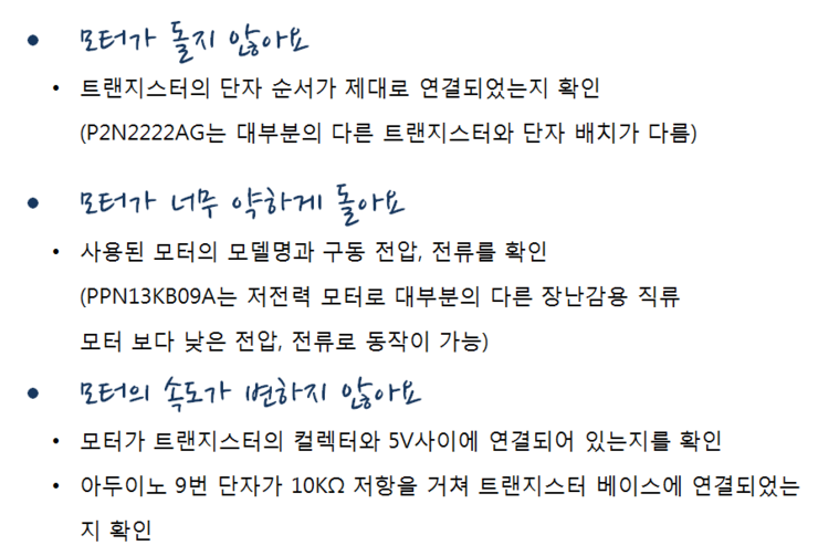
ⓞ 오류 사례
모터가 돌지 않을 때에는 우선 트랜지스터의 단자 순서가 제대로 연결되었는지 확인을 합니다. 우리가 사용하는 P2N2222Ag는 다른 대부분의 트랜지스터와는 단자 배치가 다르기 때문에 혼동하기 쉽습니다.
모터가 너무 약하게 돌 때는 사용된 모터의 모델명과 구동 전압 전류를 확인합니다. 또, 아두이노의 출력단자에 연결된 저항이 10킬로 오옴인지 확인합니다.
모터의 속도가 변하지 않을 때는 모터가 트랜지스터의 컬렉터와 5V사이에 제대로 연결되어 있는지를 확인하고 아두이노 9번 단자가 10 킬로 오옴 저항을 거쳐 트랜지스터 베이스에 연결되었는지를 합니다.
간혹 스케치 프로그램이 아두이노 보드에 탑재되지 않는 경우가 있는데 이런 경우는 대부분 직렬 포트 번호가 틀려서 그렇습니다. 아두이노 개발 환경의 메뉴 > 도구 > 시리얼 포트에서 포트 번호를 바꾸어 보세요.
직류 모터와 손바닥 컴퓨터를 이용해서 자연 바람을 흉내 낼 수 있는 선풍기를 만들어 보았습니다. 직류 모터는 선풍기 말고도 많은 곳에 사용되고 있습니다. 예. 우선. 음식 배달할 때나 간편하게 이동할 때 사용하는 전기 스쿠터,많은 사람들이 편리하게 이용하는 전철, 사진을 찍을 때 자동으로 촛점 조절이 되는 카메라의 렌즈, 인공위성을 띄우기도 하고, 산업 현장에서 물건을 조립하기도 하는 로봇팔, 집에서도 흔히 사용하는 진공 청소기, 세탁기 등등 헤아릴 수 없이 많이 사용이 됩니다.
int motorPin = 9;
int prevEnd = 127;

void setup(void)
{
   pinMode(motorPin, OUTPUT);
   randomSeed(analogRead(0));
   Serial.begin(9600);
}

void loop(void)
{
   //motorOnThenOff();
   //motorOnThenOffWithSpeed();
   //motorAcceleration();
   prevEnd = naturalWind(prevEnd);
}

void motorOnThenOff()
{
   digitalWrite(motorPin, HIGH);
   delay(3000);
   digitalWrite(motorPin, LOW);
   delay(3000);
}

void motorOnThenOffWithSpeed()
{
   analogWrite(motorPin, 200);
   delay(3000);
   analogWrite(motorPin, 50);
   delay(3000);
}

void motorAcceleration()
{
   for(int i = 0; i <= 255; i++)
   {
      analogWrite(motorPin, i);
      delay(25);
   }
   for(int i = 255; i >= 0; i\--)
   {
      analogWrite(motorPin, i);
      delay(25);
   }
   delay(5000);
}

int naturalWind(int prevEnd)
{
   int newSpeed = random(0,256);

   Serial.print("Start: ");
   Serial.println(prevEnd);
   Serial.print("End: ");
   Serial.println(newSpeed);

   if( newSpeed > prevEnd )
   {
      for(int i = prevEnd; i <= newSpeed; i++)
      {
         analogWrite(motorPin, i);
         delay(25);
      }
   }else{
      for(int i = prevEnd; i >= newSpeed; i\--)
      {
         analogWrite(motorPin, i);
         delay(25);
      }
   }
   return newSpeed;
}