

[ 기초 ] 아두이노 - 스탠드 조명 만들기
스탠드조명 만들기
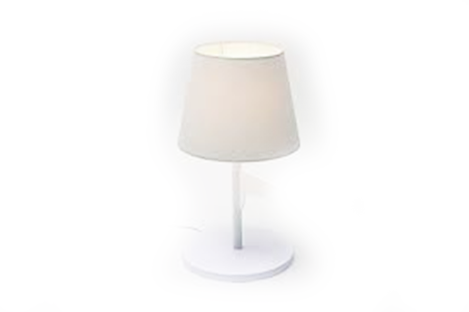
불을 켜고 필요에 따라서는 조금 더 밝게, 매우 밝게 등 밝기 조절도 가능
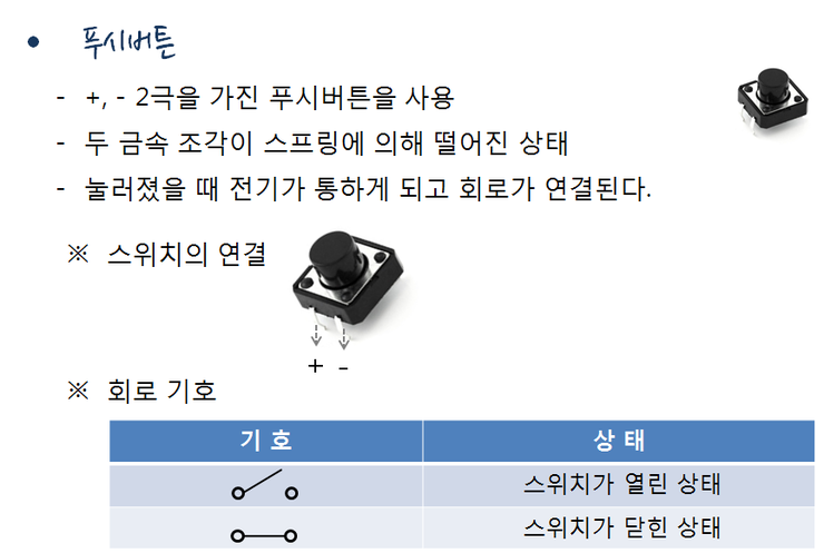
스위치는 굉장히 종류가 많습니다. MP3 스위치로 많이 사용하는 슬라이드 스위치,조이스틱이나 디지털 카메라 조작 버튼으로 많이 사용하는 멀티웨이 스위치, 마이크로 스위치 등 스위치는 종류가 다양하고 많습니다.
여기서 우리가 사용하는 스위치는 푸시 버튼이라고 하는데 +, -, 2극을 가진 아주 간단한 장치입니다.
스위치 윗부분이 플라스틱으로 덮여 있고 이 플라스틱을 열어 보면 두 금속 조각이 스프링에 의해 떨어져 있는 상태입니다.
버튼을 누르면 두 금속 조각이 서로 연결되어 전기가 흐르게 되고 손가락을 떼게 되면 다시 두 금속 조각은 떨어지게 되어 전기가 통하지 않게 됩니다.
그래서 불을 켜고 싶을 때 스위치를 눌러 두 금속 조각을 연결시키면 회로가 연결되어 스탠드 불을 켤 수가 있는 것입니다.
이 스위치는 한 쪽에 두 개씩, 모두 다리가 네 개가 있습니다. 회로에 연결할 때는 다리를 두 개만 연결하면 되는데 다리가 나란히 옆으로 나있는 부분을 앞쪽으로 해서 브레드보드에 꽂아 줍니다.
다리 하나는 +극, 다른 하나는 ?극에 연결합니다. 그러면 스위치를 눌렀을 때 켜지고 뗐을 때 꺼지는 회로를 만들수 있습니다.
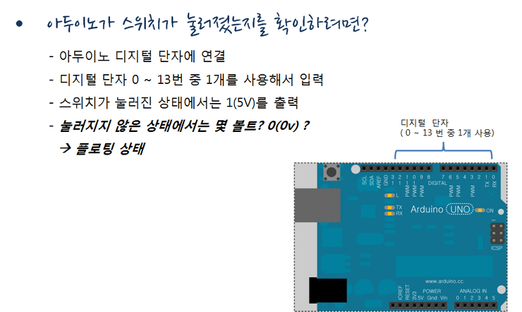
아두이노 디지털 단자 중 하나에 연결하면 되는데 문제가 하나 있습니다. 스위치가 눌러졌을 때는 회로가 연결되어 있으므로 정확히 1을 읽어 오고 전압으로는 5v를 출력 합니다. 누르지 않았을 때는 어떤 값을 읽어올까요 ? 그런 경우를 값이 정해지지 않은 상태라고 해서 플로팅 상태라고 하는데 풀다운 저항을 사용해서 이 문제를 해결합니다.
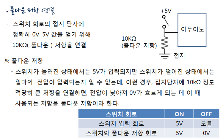
스위치가 눌러졌을 때는 회로가 완전히 연결되어 정확히 5V가 출력된다고 볼 수 있지만 누르지 않아서 스위치가 떠 있을 때는 어느 정도의 전압이 흐르는지 알 수가 없습니다.
그래서 회로가 연결되지 않았을 때 0V에 최대한 가까운 전압을 얻기 위해 스위치 회로의 접지 단자에 10kΩ정도의 비교적 큰 저항을 달아 줍니다.
이 때 사용하는 저항을 풀다운 저항이라고 하는데, 저항에 의해 전압이 낮아져 0V가 흐르게 됩니다. 그래서 스위치가 눌러졌을 때는 5V, 그렇지 않은 경우, 0V가 흐르게 됩니다.
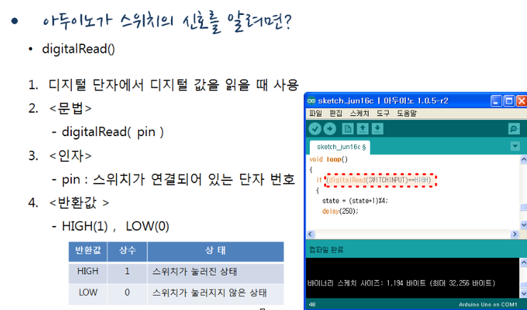
아두이노에서 스위치 신호를 알려면 digitalRead()함수를 이용해서 알 수 있습니다. digitalRead() 함수는 단자번호를 인자로 받는데 여기에 연결된 단자의 전압을 0,1값으로 반환합니다.
예를 들어, 스위치가 눌러져 3V 이상이 들어오면 HIGH(1)을 반환하고 0V가 들어오면 LOW(0)을 반환합니다.
여기서, HIGH와 LOW는 상수라고 하는데 아두이노에서 미리 1과 0으로 정의해 놓은 값이기 때문에 문자열이지만 항상 숫자 1과 0으로 사용됩니다.
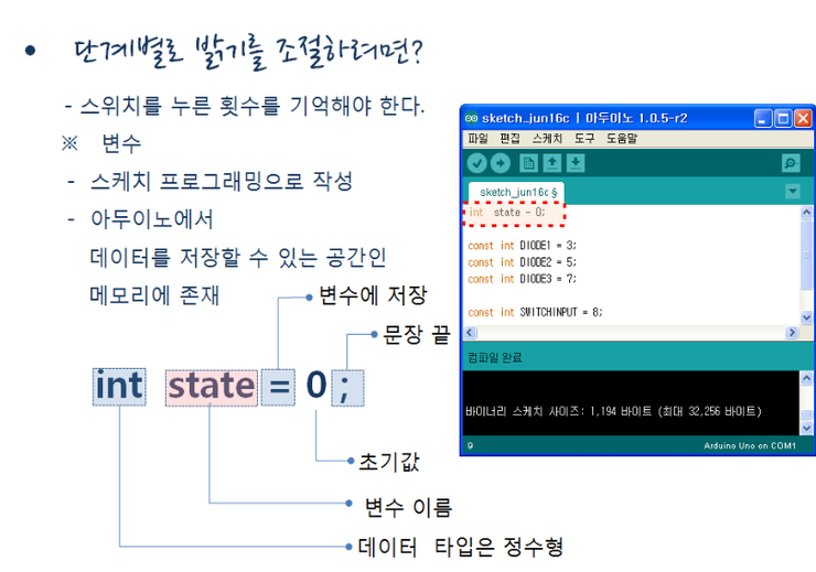
단계별로 밝기를 조절할 수 있도록 하려면 스위치를 누른 횟수를 기억해야 합니다.
변수라는 것을 사용합니다
아두이노에는 메모리라는 공간이 있어서 데이터를 저장할 수도 있고 꺼내 쓸 수도 있습니다. 저장하고 싶은 데이터의 종류가 숫자인지 문자열인지 결정하고 그 방에 이름을 붙이는데 그것을 변수라고 합니다. 그러면, 언제든 그곳에 데이터를 저장하거나 불러올 수 있습니다.
예를 들어, int state = 0 ; 이라는 문장을 살펴보겠습니다. state가 변수 이름입니다.
메모리 공간에 state라는 이름으로 방이 하나 생긴다고 생각하고. int 는 state라는 변수에 저장되는 값이 정수형이라는 것을 뜻하고 초기값으로 0을 state라는 변수에 저장하겠다는 뜻입니다. 그리고 문장 끝에는 항상 세미콜론을 붙여야 합니다.
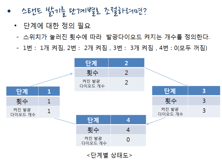
스탠드 밝기를 단계별로 조절하려면 일단, 단계에 대한 정의가 필요합니다. 스위치를 누르는 횟수에 따라 상태가 어떻게 변하는지 단계별로 미리 정의해야 합니다.
위 <단계별 상태도>에서 보는 것처럼, 총 4단계로 나누어 스위치를 누르는 횟수에 따라 단계를 정의합니다.
1단계는 스위치를 1번 누른 상태인데, 발광 다이오드 1개가 켜지고
2단계는 스위치를 2번 누른 상태인데, 발광 다이오드 2개가 켜지고,
3단계는 스위치를 3번 누른 상태인데, 발광 다이오드 3개가 켜집니다.
마지막으로 4단계는 스위치를 4번 누른 상태인데, 발광 다이오드를 모두 끄는 상태입니다.
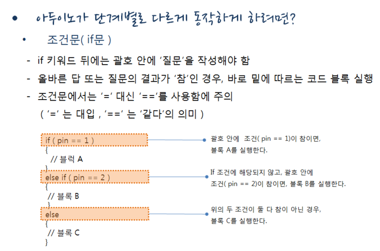
아두이노가 단계별로 다르게 동작하게 하려면 조건문이 필요합니다.
조건문은 컴퓨터에게 의사 결정을 하게 하는 명령어인데, If 문이 대표적인 조건문입니다.
if 라는 예약어 뒤에 괄호 안에 ‘질문’을 작성해야 합니다.
올바른 답 또는 질문의 결과가 참인 경우, 바로 밑에 따르는 코드 블록을 실행합니다.
조건문에서는 ‘=‘ 대신 ‘==‘를 사용합니다. ‘=‘는 대입의 의미이고, ‘==‘는 같다는 것을 의미 합니다.
아래 조건문 예를 보시면, If ( pin == 1 ) 의 경우, 괄호 안에 pin이라는 변수의 값이 1이면, 아래 코드 블록 A를 실행합니다. 그리고 Else if ( pin == 2 )의 경우는, 위의 if 조건에는 해당되지 않고, Pin ==2 이면, 코드 블록 B를 실행합니다. 마지막으로, 이의 두 조건의 어디에도 해당이 되지 않는 경우, 블록 C를 실행하게 됩니다.
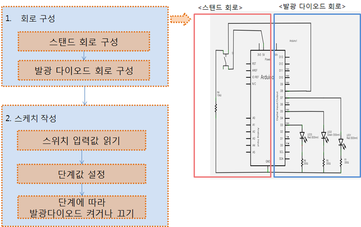
아두이노에 스위치를 연결한 회로와 발광 다이오드 3개를 연결한 회로
이 회로는 두 개 회로의 조합인데 스위치 입력회로와 발광 다이오드 출력 회로의 조합입니다. 스위치 입력 회로를 한번 살펴보면, 스위치의 한 쪽 다리는 아두이노 5V단자에 연결하고 다른 한 쪽 다리는 10K옴 저항과 연결해 아두이노의 8번 입력 단자에 연결해 스위치 입력 회로를 만들어 줍니다. 그리고 발광다이오드 출력 회로인데 3개의 다이오드를 3번, 5번, 7번 단자에 연결하고 저항과 함께 연결해 줍니다.
이렇게 회로가 다 구성되고 나면 스케치를 작성해야겠지요. 먼저, 스위치 입력값을 읽고 스위치를 누른 상태이면 단계값을 설정합니다. 그리고 나서 단계에 따라 발광다이오드를 켜거나 끄도록 스케치를 작성하면 됩니다.
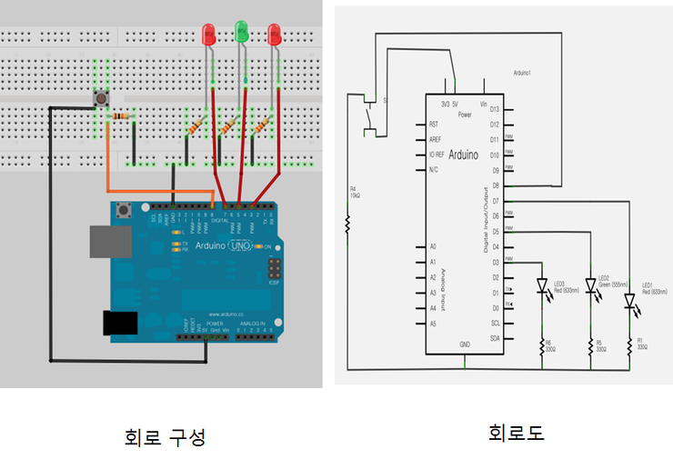
회로구성대로 브레드보드 위에 부품들을 배치하고 점퍼선을 이용하여 연결을 해줍시다.
모두 연결한 뒤에는 부품의 방향과 단자 번호 등을 다시 한번 확인 합니다.
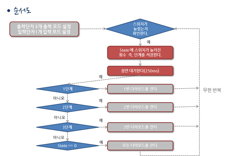
처음 setup() 함수 에서는 출력단자 세 개를 출력 모드로 설정하고 입력단자 1개를 입력모드로 설정합니다. 그리고 스위치가 눌러진 횟수를 확인해서 단계를 저장합니다.
그리고, 250 마이크로초 정도로 아주 짧게 대기하는데, 스위치를 누른 순간을 제대로 감지하기 위한 목적입니다.
1단계이면, 1번 다이오드를 켜고 2단계이면, 2번 다이오드를 켜고 3단계이면, 3번 다이오드를 켭니다. 4단계이면, 모든 다이오드를 끄도록 합니다.이 과정을 무한 반복합니다.
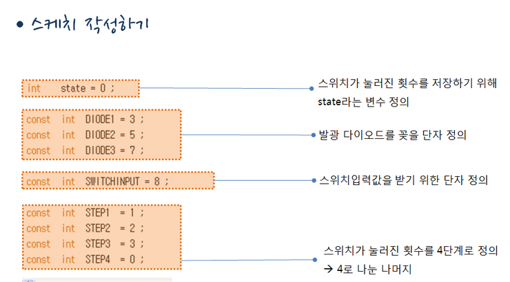
우선 변수와 상수를 미리 정의했어요. 스위치가 눌러진 횟수를 저장하기 위해 State라는 변수를 선언했고 발광 다이오드를 꽂을 단자 3개를 DIODE1, DIODE2, DIODE3라는 이름의 상수로 정의 했습니다. 그리고 스위치의 입력값을 받기 위한 단자 이름을 SWITCHINPUT으로 지정하고 스위치가 눌러진 횟수를 4단계로 지정하기 위해 STEP1, STEP2, STEP3, STEP4라는 상수 4개를 선언하였습니다.
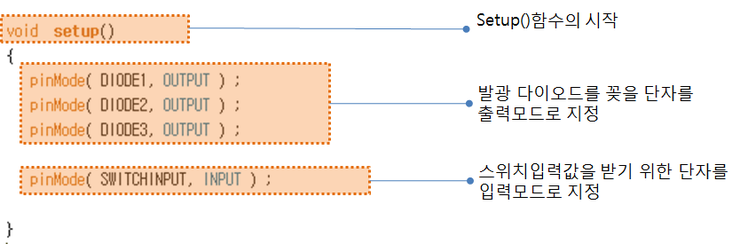
Setup()함수에서 동작이 일어나기 전에 초기 환경을 설정 합니다. 아래 발광 다이오드를 꽂을 단자, DIODE1, DIODE2, DIODE3를 OUTPUT 출력모드로 지정했습니다. 그리고 스위치 입력을 위해 선언된 SWITCHINPUT을 입력모드로 지정합니다.
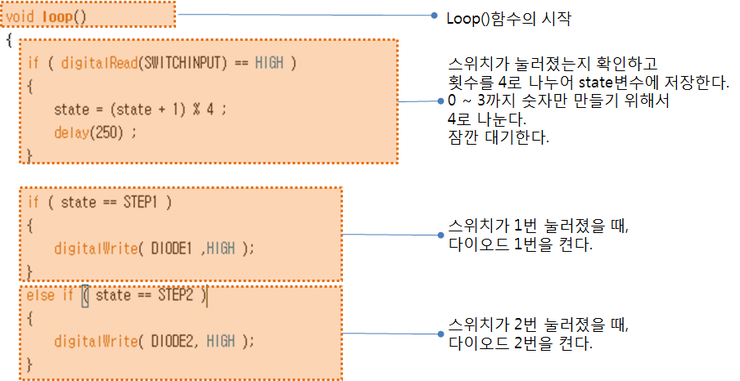
loop()함수인데 실질적인 동작이 무한히 반복됨을 알려줍니다. 먼저, digitalRead()함수를 호출해서 스위치가 눌러졌는지를 확인하고 스위치가 눌러진 횟수를 4로 나누어 나머지값을 사용하는데이것은 4단계로만 관리하기 위한 목적입니다. 그리고, 스위치가 1번 눌러졌을 때 DIODE1번을 켜고 스위치가 2번 눌러졌을 때 DIODE2번을 켭니다.
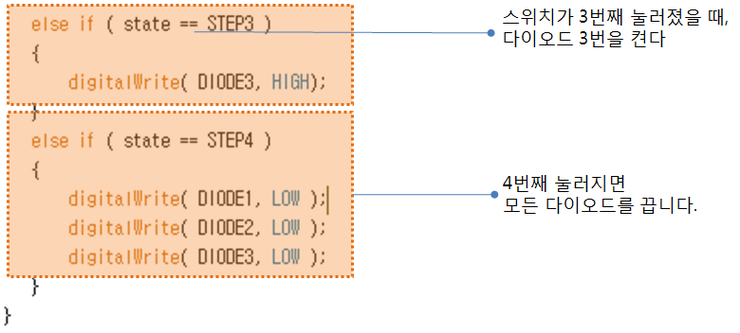
스위치가 3번째 눌러지면 DIODE3을 켜고 4번째 눌러지면 모든 다이오드를 끕니다.
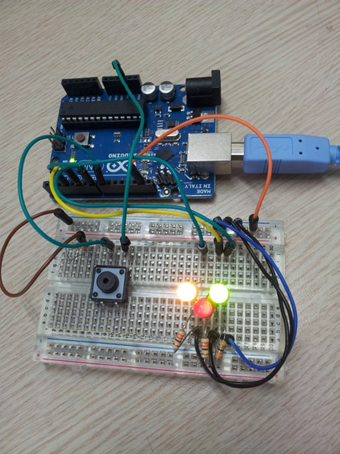
< 완성된 사진>
가정집에는 어디에나 있는 전등 스위치, 리모컨 버튼에도 전원을 제어하거나 채널을 바꿀 때, TV에도, 엘리베이터 에도, 선풍기에도, 컴퓨터도 우리가 뭔가 동작을 선택할 수 있는 전자제품에는 거의 스위치가 들어가는 것입니다.
int  state = 0;

const int DIODE1 = 3;
const int DIODE2 = 5;
const int DIODE3 = 7;

const int SWITCHINPUT = 8;

const int STEP1 = 1;
const int STEP2 = 2;
const int STEP3 = 3;
const int STEP4 = 0;

void setup()
{
    pinMode( DIODE1, OUTPUT );
    pinMode( DIODE2, OUTPUT );
    pinMode( DIODE3, OUTPUT );

    pinMode( SWITCHINPUT, INPUT );
}

void loop()
{
    if( digitalRead(SWITCHINPUT) == HIGH )
    {
        state = (state + 1)%4;
        delay(250);
    }

    if ( state == STEP1){
        digitalWrite( DIODE1, HIGH );
    }else if ( state == STEP2 ){
        digitalWrite( DIODE2, HIGH );
    }else if ( state == STEP3 ){
        digitalWrite( DIODE3, HIGH );
    }else if ( state == STEP4 ){
        digitalWrite( DIODE1, LOW );
        digitalWrite( DIODE2, LOW );
        digitalWrite( DIODE3, LOW );
    }
}댓글 1개
- 주피터댓글