

[기초] 아두이노 실습 - 신호등 만들기
신호등 만들기
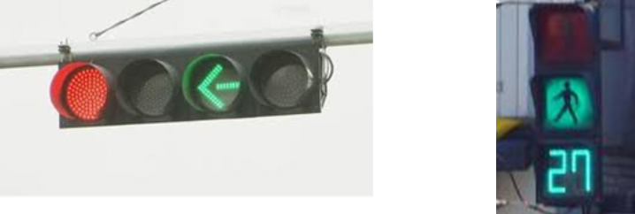
신호등을 자세히 들여다 보면 신호등 불빛은 굉장히 많은 점들로 구성되어 있는데 이 점들 하나 하나가 전구와 같이 빛을 내고 있는 것을 알 수 있어요.
이러한 것들을 발광다이오드(LED)로 구성 되어 있습니다.
빨간등과 파란등을 번갈아 켜지게 하려면 ?
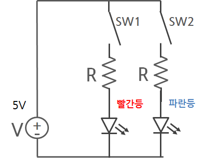
ⓞ 전원, 저항, 발광다이오드 2개에 스위치가 각각 연결된 회로도
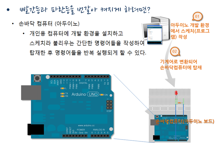
ⓞ 아두이노 실행
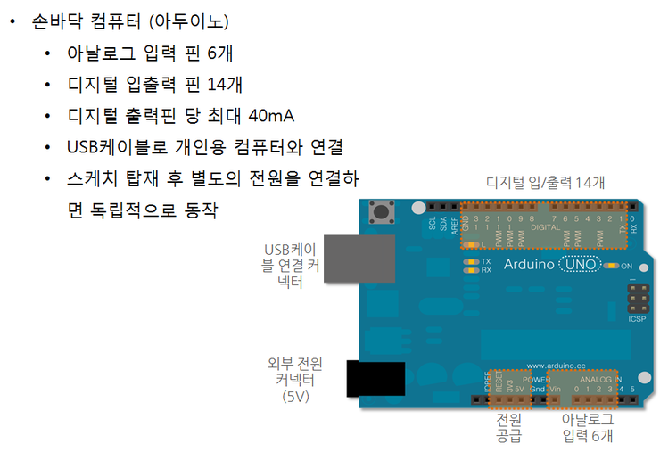
ⓞ 아두이노 구성
가장 대표적인 손바닥 컴퓨터로는 아두이노라고 하는 것이 있는데요. 아두이노를 보면 아날로그 신호를 입력 받을 수 있는 핀이 a0 ~ a5까지 6개, 디지털 입력 또는 출력으로 사용할 수 있는 핀이 0 ~ 13까지 14개가 있습니다.
디지털 출력 핀에서는 최대 40mA까지 전류가 흘러나올 수 있습니다. 더 많은 전류가 흘러나오도록 회로를 구성하면 아두이노 내부의 부품들이 견디지 못하고 고장 날 수 도 있기 때문에 주의를 해야 합니다.
아두이노는 개인용 컴퓨터와 연결할 수 있도록 USB 커넥터가 있어서 개인용 컴퓨터로 부터 스케치(프로그램)를 전송 받거나 통신을 할 수 있고, 동시에 5V의 전원도 공급받을 수 있습니다.
컴퓨터와 연결되어 있지 않을 때는 별도의 외부 전원 커넥터를 통해서 전원을 공급받을 수 도 있습니다.
일단 컴퓨터로 부터 스케치를 전송 받으면 손바닥 컴퓨터는 개인용 컴퓨터와는 무관하게 혼자서 스케치를 실행합니다. 따라서 외부 전원을 공급해 주면 USB케이블을 연결하지 않아도 혼자서 동작을 합니다.
① 스케치 구조
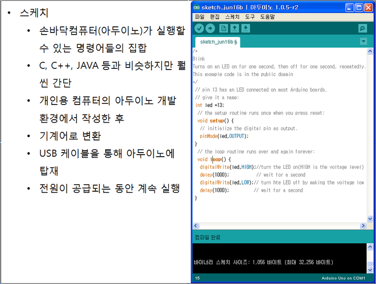
스케치는 우리가 흔히 컴퓨터에서 프로그램이라고 부르는 컴퓨터 언어의 일종인데요.아두이노에게 명령을 내리는 명령어들의 묶음을 영어 문장 비슷하게 써 놓은 것입니다.
개인용 컴퓨터에서 프로그래밍을 할 때 사용하는 C, C++, JAVA 등의 언어와 아주 비슷하지만 훨씬 쉽고 간단합니다.
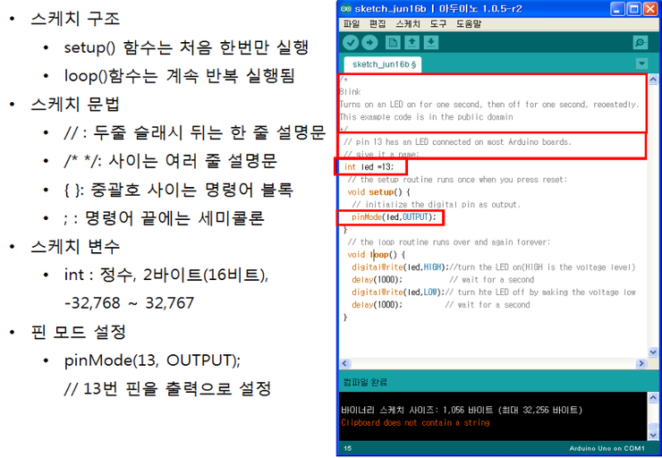
스케치에는 중요한 두 개의 함수가 꼭 필요한데 하나는 setup() 함수이고, 또 하나는 loop() 함수입니다. setup() 함수는 스케치가 처음 실행될 때 한 번만 실행되고, loop() 함수는 이후 계속 무한 반복해서 실행됩니다.
스케치에는 실제 실행되지는 않고 읽는 사람의 이해를 돕기 위한 설명문을 넣을 수 있는데 // 는 한 줄 설명문을 쓸 대, /* */ 는 여러 줄에 걸쳐 설명문을 작성할 때 사용합니다.
명령어들을 하나의 블럭으로 묶을 때는 중괄호 { }를 사용하고, 명령어의 뒤에는 세미콜론을 붙여 줍니다.
스케치에는 숫자를 넣어둘 수 있는 여러가지 변수를 사용할 수 있는데, 가장 많인 사용하는 변수는 정수형 변수로서 int 라고 쓰고 뒤에 변수명을 적어주면 됩니다.
정수형 변수는 내부적으로 2바이트, 즉 16비트의 크기를 차지하고, -32,768 ~ 32,767까지의 정수를 담을 수 있습니다.
아두이노 보드의 디지털 입/출력 단자를 사용하기 위해서는 우선, 단자 모드를 설정해주어야 하는데 pinMode() 함수를 사용하면 쉽게 할 수 있습니다. pinMode()함수의 괄호안에는 설정하고자 하는 단자번호와, 입/출력을 결정하는 INPUT 또는 OUTPUT 상수를 지정해주면 됩니다.
단자모드 설정은 실제 단자를 사용하기 전에 한 번만 해주면 되니까 setup() 함수 안에서 사용하면 됩니다.
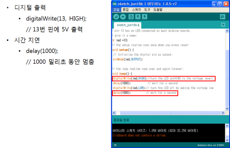
디지털 입/출력 단자를 출력 모드로 설정한 후에는 digitalWrite() 함수를 사용해서 실제 출력을 할 수 있습니다. digitalWirte() 함수의 괄호안에, 단자 번호와 HIGH 또는 LOW 상수를 써주면, HIGH일 때는 5V, LOW 일 때는 0V가 출력됩니다.
아두이노가 일정 시간 동안 아무일도 하지 않도록 하려면 delay() 함수를 사용하면 됩니다.
delay()함수의 괄호안에 숫자를 써주면 지정한 숫자에 해당하는 밀리초 동안 아두이노가 멈춰있게 됩니다.
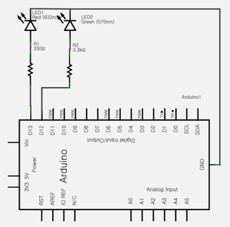
아두이노의 13번 단자에 저항을 연결하고, 거기에 빨간색 발광 다이오드의 애노드를 연결합니다. 12번 핀에도 역시 저항을 연결하고, 거기에 파란색 발광 다이오드의 애노드를 연결합니다. 두 발광 다이오드의 캐소드는 모두 아두이노의 그라운드에 연결해 줍니다.
두 발광 다이오드에 흐르는 전류는 20mA이하여야 하니까 두 저항의 값은 250 오옴 이상인 것을 사용하는 것이 좋습니다. 그리고 스케치를 작성해서 13번 단자와 12번 단자를 출력으로 설정한 후에 5초 마다 5V와 0V를 번갈아 출력해주면 될 것 같아요.
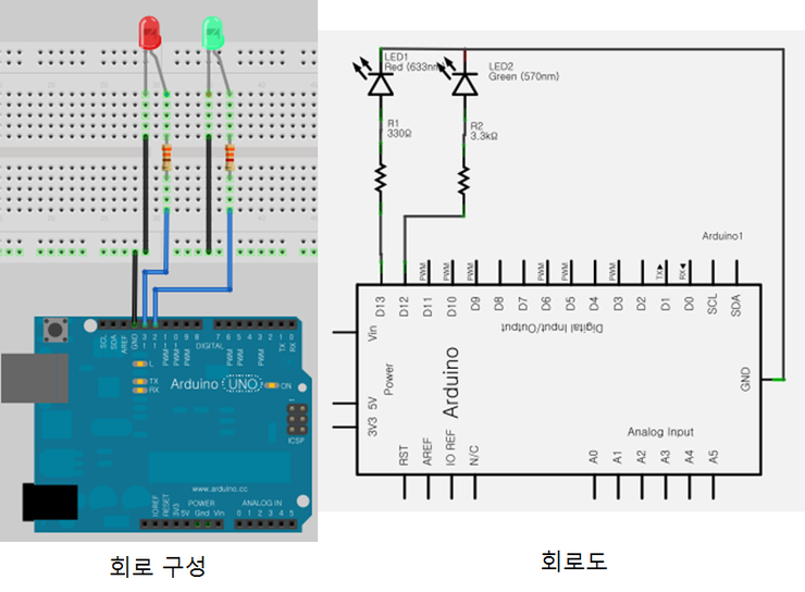
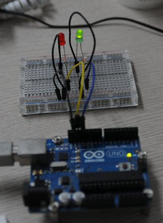
회로구성대로 브레드보드 위에 부품들을 배치하고 점퍼선을 이용하여 연결을 해줍시다.
모두 연결한 뒤에는 부품의 방향과 단자 번호 등을 다시 한번 확인 해보세요.
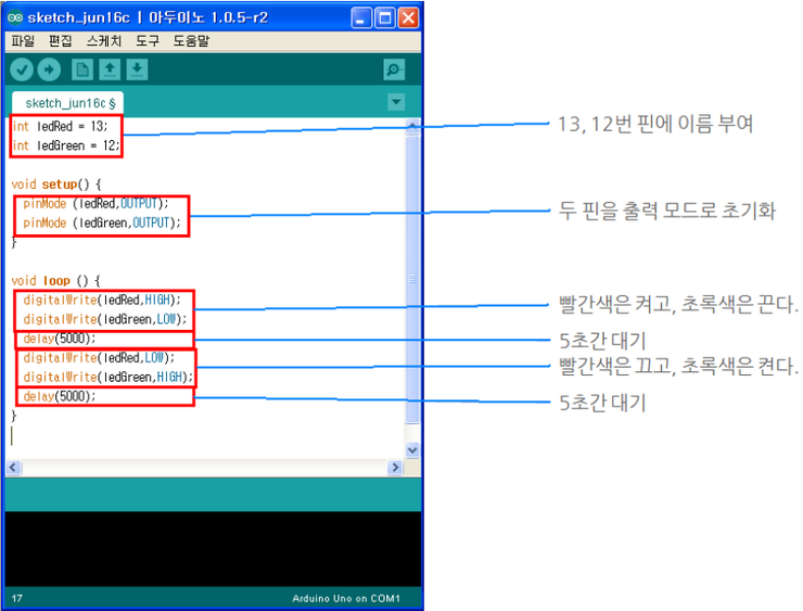
정수형 변수 ledRed와, ledGreen을 선언해서 13과 12를 대입했습니다.
이렇게 변수를 사용하면 숫자를 계속 외우지 않아도 되고, 나중에 단자 번호를 바꾸게 될 때에도 처음 변수를 선언한 부분에서만 바꿔주면 되니까 편리합니다.
setup() 함수에서는 pinMode함수를 두번 호출하여 ledRed와 ledGreen 단자를 모두 출력으로 설정하였습니다. 그 다음 loop()함수에서는 우선, digitalWrite() 함수를 두 번 호출하여 ledRed는 켜고, ledGreen은 끕니다.
그 다음 delay(5000) 함수를 호출하여 5초간 대기하도록 합니다. 그 다음 다시 digitalWrite() 함수를 두 번 호출하여 ledRed는 끄고, ledGreen은 켭니다.
다시 delay(5000)함수를 호출하여 5초간 대기하도록 합니다.
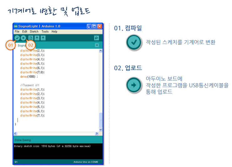
아두이노 개발 환경 도구 모음의 첫번째 체크 표시 아이콘의 버튼을 클릭하면 작성된 스케치를 기계어로 변환합니다. 오류가 있으면 아랫부분의 창에 오류 메시지가 표시되고, 이 메시지를 참고하여 잘못된 부분을 찾아 수정을 해야됩니다.
오류가 반복되면 오류가 완전히 없어질 때까지 이 과정을 반복해야 되겠지요. 이런 과정을 벌레를 잡는다는 의미의 디버깅이라고 합니다.더 이상 오류가 발생하지 않으면, 옆에 있는 업로드 버튼을 클릭하여 변환된 기계어 코드를 아두이노 보드에 업로드합니다.
int ledRed = 13;
int ledGreen = 12;

void setup()
{
  pinMode (ledRed,OUTPUT);
  pinMode (ledGreen,OUTPUT);
}

void loop()
{
   digitalWrite(ledRed,HIGH);
   digitalWrite(ledGreen,LOW);
   delay(5000);

   digitalWrite(ledRed,LOW);
   digitalWrite(ledGreen,HIGH);
   delay(5000);
}