[ Basics ] Arduino Practice - Creating a Street Light that Gradually Brightens as It Gets Dark

주피터 · 2019-10-28 · 7
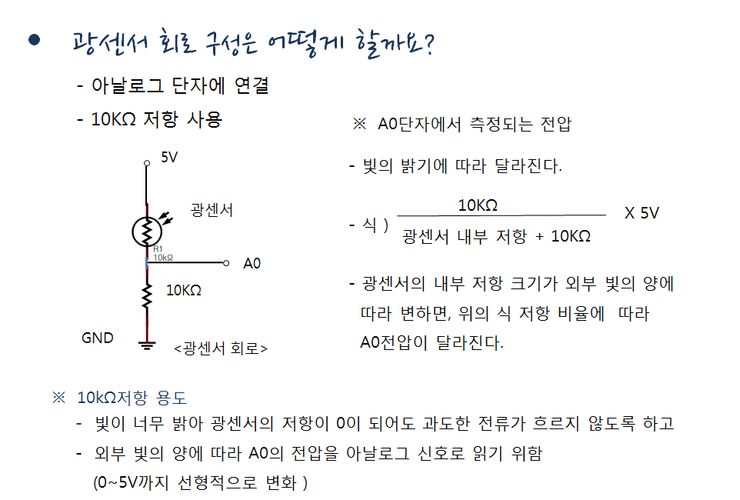
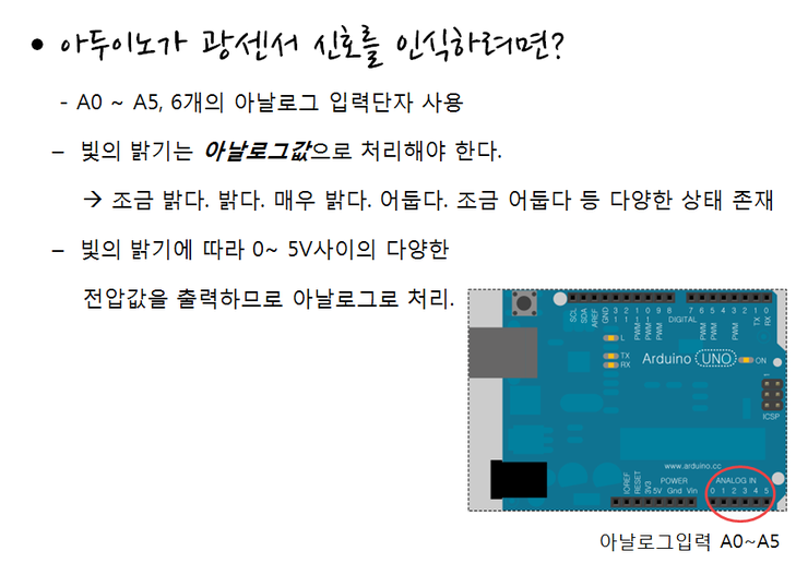
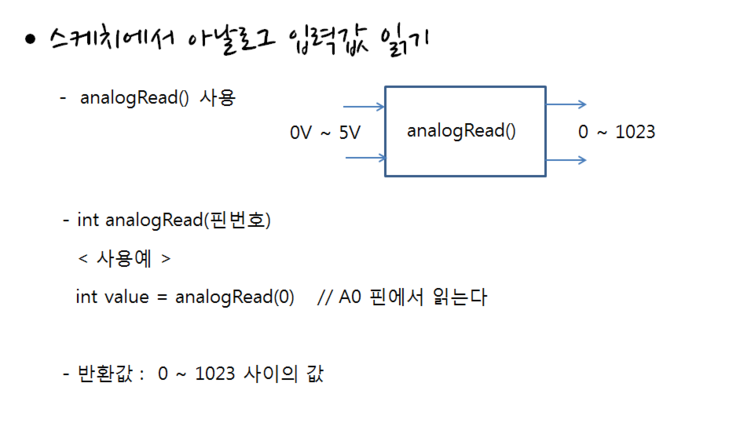
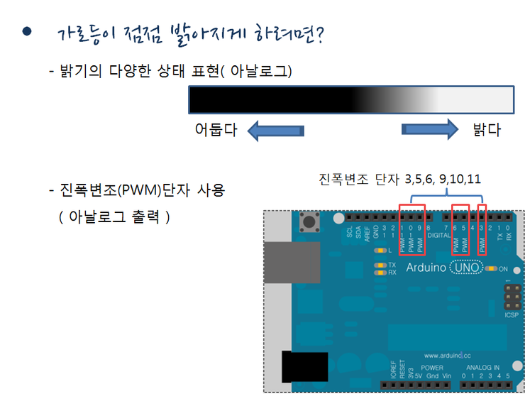
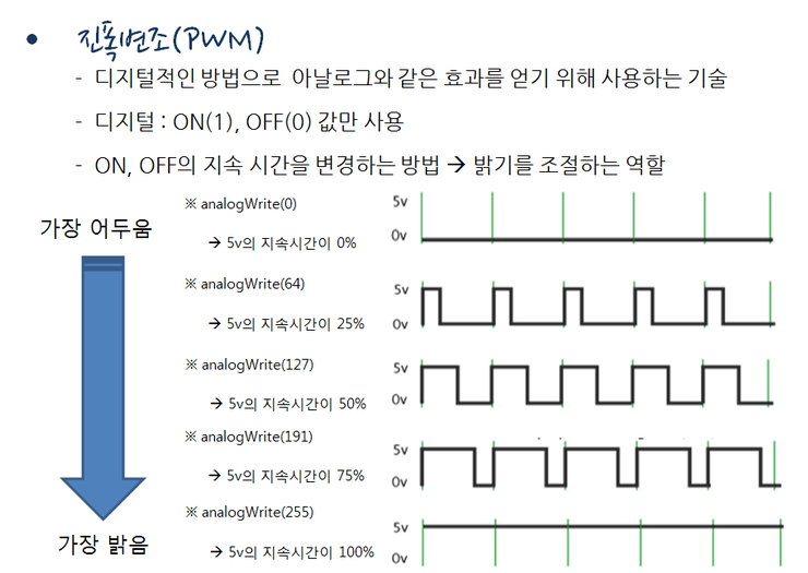
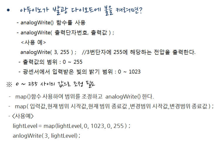
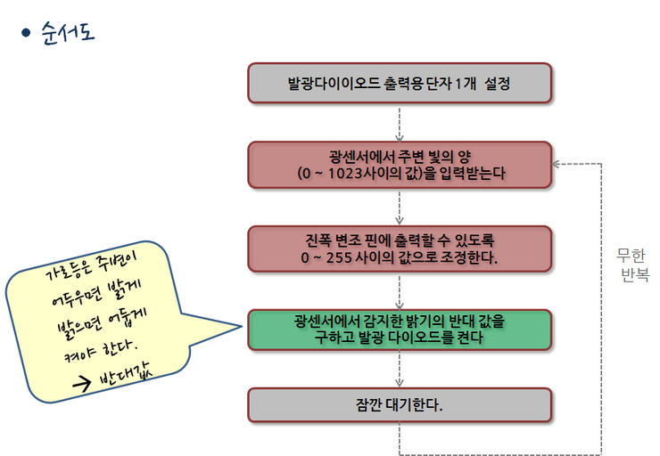
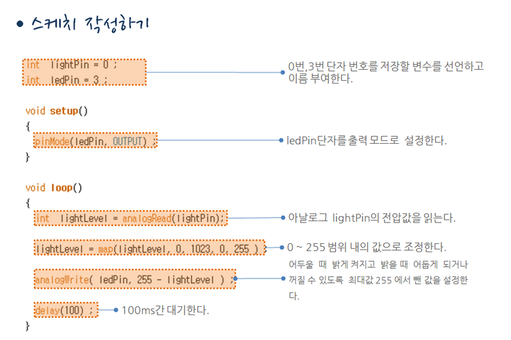
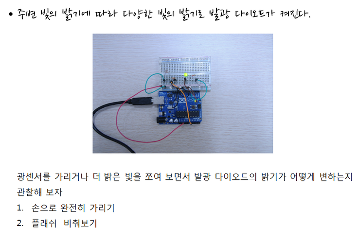
You've probably seen street lights turn on one by one as it gets dark in the evening. It seems like there's no one around and no one is pressing a switch to turn them on, so how do street lights turn on automatically? It's because the street light recognizes the brightness of its surroundings and automatically turns on. Let's make a street light together and see how it turns on automatically and gradually gets brighter. A light sensor is an electronic component that measures the amount of light and converts it into an electrical signal for output. A light sensor is a non-polar element without polarity for +/-, similar to a resistor, so there's no need to consider direction when configuring a circuit. And it has a simple internal circuit structure combined with one resistor—when the brightness of light increases, the internal resistance value decreases, and when it darkens, the internal resistance value increases. Therefore, different voltages are output according to changes in internal resistance value. ⓞ Light sensor circuit configuration Looking at how to configure a light sensor circuit, as shown in the diagram, we use an analog terminal to read the output voltage and connect a large resistor of about 10K ohms to configure the circuit. One leg of the light sensor is connected to 5V, the other is connected to the analog input terminal, and one 10K ohm resistor is connected between the analog input terminal and ground. The voltage measured at terminal A0 varies depending on the brightness of the light. When expressed as a formula, it appears as shown in the diagram, and when the light sensor's internal resistance changes according to the amount of external light, the A0 voltage changes according to the resistance ratio in the above formula. Why do we use such a large resistor of about 10K ohms? It's to prevent excessive current from flowing even if the light sensor's resistance becomes 0 due to very bright light, and to allow the A0 voltage to change linearly from 0 to 5V. ⓞ Receiving analog input from the voltage value output by the light sensor To have the Arduino recognize the light sensor signal, it must be connected to the analog input terminal. Arduino has 6 analog input terminals from A0 to A6, and you can use any one of them. We mentioned that the light sensor circuit is connected to the analog terminal. Computers can only recognize two values, 0 and 1, which is called digital. However, in the world we live in, there are countless things that cannot be expressed with just two values, 0 and 1. For example, the brightness of light doesn't just have two values: bright and dark. It has a wide variety of values such as bright, somewhat bright, very bright, dark, very dark, and so on. This kind of representation with diverse values is called analog. Therefore, since the brightness of light must be processed as analog values rather than digital values, it is connected to the analog terminal. ⓞ Reading analog input values with the analogRead() function To read analog input values in a sketch, use the analogRead() function when programming the sketch. As shown in the diagram, if the light sensor outputs a voltage value of 0V to 5V, the analogRead() function receives the 0V to 5V voltage value output by the light sensor and converts it to a value between 0 and 1023. So the analogRead() function takes a terminal number as an argument, reads the voltage value of that terminal, converts it to a value between 0 and 1023, and returns it. Therefore, it returns 1024 different values. ⓞ Amplitude modulation for LED brightness control To make a street light gradually get brighter, there isn't just a bright and dark state—there are various states of gradually darkening and brightening, so analog values rather than digital values must be used. Therefore, we use the analog output terminal. It's called the amplitude modulation terminal. On the Arduino board, if you look below the digital pins, you can connect a light-emitting diode to pins 3, 5, 6, 9, 10, and 11 marked with PWM. ⓞ Amplitude modulation Amplitude modulation is a method to achieve an analog-like effect using a digital method. Although it uses only digital ON (1) and OFF (0) values, it can control the brightness of light by changing the duration. For example, if the output value is 0, the 5V duration is 0%, so only 0V continues to flow and the LED is off. If the output value is set to 127, it becomes 50% of the 255 range, so the 5V duration is 50%, resulting in medium brightness. If it's set to 255, it becomes 100% and reaches the brightest state. Adjusting the duration of 0 and 1 according to the output value in this way to create an analog effect is called amplitude modulation. ⓞ LED output using analogWrite() To have the Arduino turn on a light-emitting diode, use the analogWrite() function. You pass the output terminal number and output value as arguments. Here, the output value is between 0 and 255. The brightness of light received from the light sensor is in the range of 0 to 1023, so adjustment of the range is necessary. The function used for this is the map() function. When you put the current range value and the range value you want to adjust into the map() function, it returns a value that matches the adjusted range. So you first use the map() function to adjust the range of values, and then use the returned value as the output value for analogWrite(). ⓞ Sketch flowchart Looking at the flowchart as shown in the diagram, first we set one pin for light-emitting diode output. This part is a preparation process for actual operation. Next, we receive a voltage value between 0 and 1023, then adjust the range to a value between 0 and 255. And we find the opposite value of that value. Because a street light must be bright when the surroundings are dark and dark when it's bright, we send the opposite value of the ambient brightness value to the terminal connected to the light-emitting diode to turn it on. To remove unwanted false signals, we pause briefly and infinitely repeat the above process. Integer variables lightPin and ledPin are declared and assigned 0 and 3 respectively. This means we will use terminals 0 and 3. In the setup() function, the pinMode function is called to set the ledPin to output. Next, the loop() function begins. The statements inside the loop() function repeat infinitely. First, we need to read the current ambient light brightness from the light sensor, so we call the analogRead() function to read the voltage value of lightPin and store it in the variable lightValue. Next, we call the map() function to adjust it to a value within the 0 to 255 range and store it back in lightValue. Now we call the analogWrite() function and pass 255 minus lightValue as an argument. The reason is that we need to set it so that it's bright when the ambient brightness is dark and dark when it's bright. Then we call the delay(100) function to pause for 100 milliseconds. Cover the light sensor and check if the light-emitting diode turns on. Then expose it to light and also check if the light-emitting diode turns off. If you have a flashlight, you can shine it on the sensor as well. The light-emitting diode will turn on with various levels of brightness depending on the ambient light brightness recognized by the light sensor. ``` int lightPin = 0; int ledPin = 3; void setup() { pinMode(ledPin, OUTPUT); } void loop() { int lightLevel = analogRead(lightPin); lightLevel = map(lightLevel, 0, 1023, 0, 255); analogWrite(ledPin, 255 - lightLevel); delay(100); } ```
7
댓글 0
등록된 댓글이 없습니다.