

[로봇팔 제어 프로젝트 3] 조이스틱 입력값 확인 테스트
· 2019-11-14 · 4
본 실습을 통해 아날로그 입력과 조이스틱 센서에 대해 이해한다.
준비물 : Arduino, 조이스틱 1개
내용 : 조이스틱을 아두이노에 연결하여 조이스틱의 조종에 따라 아날로그 입력값이 어떤 식으로 입력되는지 시리얼 모니터를 통해 확인한다. 이 실습을 통해 조이스틱을 움직였을 때 아날로그 값이 어떻게 변하는지 확인하고 이를 토대로 서보모터가 움직일 수 있게 하는 아날로그 값의 범위를 결정한다.
회로 연결은 다음과 같다.
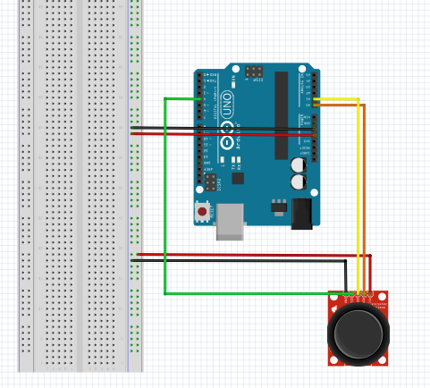
실제 실습은 조이스틱 9핀을 사용하였지만 fritzing에는 없으므로 일반적으로 사용하는 5핀짜리 조이스틱을 fritzing에서 사용하였다.
조이스틱은 x, y 축으로 아날로그 입력이 가능하고, z 축으로 버튼을 누르면 디지털 입력이 가능하다. x축을 담당하는 VER핀을 A0번에 연결하였고, y축을 담당하는 HOR핀을 A1핀에 연결하였다. 또한 z축 디지털 입력을 담당하는 SEL핀을 4번핀에 연결하였다.
코드는 다음과 같다.
#include <Servo.h> //헤더파일 포함
const int X_AXIS = A0; //x축 아날로그 입력핀 0번 지정
const int Y_AXIS = A1; //y축 아날로그 입력핀 1번 지정

void setup() {
  // put your setup code here, to run once:
  Serial.begin(9600); //시리얼 모니터 사용
}

void loop() {
  // put your main code here, to run repeatedly:
  int xVal = analogRead(X_AXIS); //X축값 읽음
  int yVal = analogRead(Y_AXIS); //Y축값 읽음
  int pushBtn = digitalRead(4);
  Serial.print("Btn : ");
  Serial.print(pushBtn);
  Serial.print("   ");
  Serial.print("X:  ");
  Serial.print(xVal);
  Serial.print("   ");
  Serial.print("Y : ");
  Serial.println(yVal);
  delay(500);
}
동작영상
4
댓글 0개
등록된 댓글이 없습니다.