

[로봇팔 제어 프로젝트 4] 2개의 조이스틱을 이용한 5관절 로봇팔 제어
본 실습은 이전의 로봇팔 프로젝트 1, 2, 3을 통해 서보모터, 조이스틱 등을 이해한 것을 바탕으로 로봇팔을 제작한다.
준비물 : Arduino, 조이스틱 2개, 서보모터 5개, 배터리, 로봇팔 프레임
내용 : 2개의 조이스틱 아날로그 입력값을 이용하여 서보모터 5개를 동작시킨다. 또한 각각의 조이스틱 버튼을 통해 집게를 움직일 수 있도록 제작하였다. 로봇팔의 집는 동작이 너무 빠르면 집는 물체를 파손시킬 수 있기 때문에 각각의 모터 속도를 다르게 계산하였다.
회로 연결은 다음과 같다.
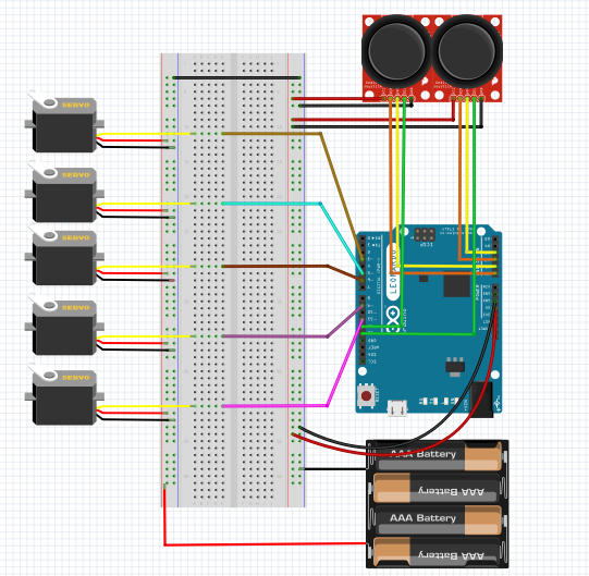
실제 모터는 6~7V에서 동작을 하는 서보모터를 사용하였기 때문에 아두이노가 아닌 별도의 전원을 공급하였다. fritzing을 보면 두개의 전원을 하나의 ground로 묶은것을 볼 수 있다.
1번(왼쪽) 조이스틱의 경우
x축 -> A0 (아날로그 입력핀)
y축 -> A1 (아날로그 입력핀)
z축 -> 12 (디지털 입력핀)
핀에 연결하였고,
2번(오른쪽) 조이스틱의 경우
x축 -> A2 (아날로그 입력핀)
y축 -> A3 (아날로그 입력핀)
z축 -> 13 (디지털 입력핀)
핀에 연결하였다.
또한 서보모터의 입출력핀 연결은 위에서부터 3,5,6,9,10으로 연결하였다.
코드는 다음과 같다.
#include<Servo.h> //헤더파일 포함
Servo servo1; //변수 선언
Servo servo2;
Servo servo3;
Servo servo4;
Servo servo6;

int motor1 = A0; // 모터1(회전축을 담당하는 모터)의 조종을 담당하는 아두이노 A0핀에 연결
int motor2 = A1; // 모터2(중앙 위아래 관절을 담당하는 모터)의 조종을 담당하는 아두이노 A1핀에 연결
int motor3 = A3; // 모터3(집게의 위아래 관절을 담당하는 모터)의 조종을 담당하는 아두이노 A3핀에 연결
int motor4 = A2; // 모터4(집게를 좌우로 돌리는 관절을 담당하는 모터)의 조종을 담당하는 아두이노 A2핀에 연결
int angle1, angle2, angle3, angle4, angle6;
void setup() {
  // put your setup code here, to run ongnce:
  servo1.attach(5); //회전축을 담당하는 모터 => 5번 지정
  servo1.write(90);
  servo2.attach(3); //중앙 위아래 관절을 담당하는 모터 => 3번 지정
  servo2.write(90);
  servo3.attach(6); //집게의 위아래 관절을 담당하는 모터 => 6번 지정
  servo3.write(90);
  servo4.attach(9); //집게를 좌우로 돌리는 관절을 담당하는 모터 => 9번 지정
  servo4.write(90);
  servo6.attach(10); //집게를 담당하는 모터 => 10번 지정
  pinMode(12,INPUT); //왼손용 조이스틱의 디지털 입출력 핀12번 지정
  pinMode(13,INPUT); //오른손용 조이스틱의 디지털 입출력 핀13번 지정
  servo6.write(90);
}

void loop() {
    if ((analogRead(motor1) <= 450) && (analogRead(motor1) >= 0))
   //사용자가 원치 않는 조이스틱의 입력을 막기 위해 조이스틱 아날로그 입력값이 중간 값의 -50까지 범위를 제외시킴
  {
    angle1 = angle1 - ((analogRead(motor1) - 500)/50 );
    //로봇팔의 회전속도를 조절하기 위해 실험을 통해 나온 적절한 속도값을 계산하여 구함
    if (angle1 <= 0)
    {
        angle1 = 0;
    }
    servo1.write(angle1);
  }
  else if((analogRead(motor1) >= 600) && (analogRead(motor1) <= 1023))
  //사용자가 원치 않는 조이스틱의 입력을 막기 위해 조이스틱 아날로그 입력값이 중간 값의 +100까지 법위를 제외시킴
  {
    angle1 = angle1 + ((500 - analogRead(motor1))/50 );
    if (angle1 >= 180)
    {
        angle1 = 180;
    }
    servo1.write(angle1);
  }
  delay(15);
  if ((analogRead(motor2) <= 450) && (analogRead(motor2) >= 0))
  {
    angle2 = angle2 + ((500 - analogRead(motor2))/150 );
    //중앙 관절을 담당하는 motor2의 경우 속도가 빠를 경우 물체를 집을 때 컨트롤 하기가 어렵기 때문에 다른 모터에 비해 속도를 낮춤
    if (angle2 >= 180)
    {
        angle2 = 180;
    }
    servo2.write(angle2);
  }
  else if((analogRead(motor2) >= 600) && (analogRead(motor2) <= 1023))
  {
    angle2 = angle2 - ((analogRead(motor2) - 500)/150 );
    if (angle2 <= 0)
    {
        angle2 = 0;
    }
    servo2.write(angle2);
  }
  delay(15);

  if ((analogRead(motor3) <= 450) && (analogRead(motor3) >= 0))
  {
    angle3 = angle3 + ((500 - analogRead(motor3))/50 );
    if (angle3 >= 170)
    {
        angle3 = 170;
    }
    servo3.write(angle3);
  }
  else if((analogRead(motor3) >= 600) && (analogRead(motor3) <= 1023))
  {

        angle3 = angle3 - ((analogRead(motor3) - 500)/50 );
    if (angle3 <= 0)
    {
        angle3 = 0;
    }
    servo3.write(angle3);
  }
  delay(15);


  if ((analogRead(motor4) <= 450) && (analogRead(motor4) >= 0))
  {
    angle4 = angle4 - ((analogRead(motor4) - 500)/50);
    if (angle4 <= 0)
    {
        angle4 = 0;
    }
    servo4.write(angle4);
  }
  else if((analogRead(motor4) >= 600) && (analogRead(motor4) <= 1023))
  {
        angle4 = angle4 + ((500 - analogRead(motor4))/50 );
    if (angle4 >= 170)
    {
        angle4 = 170;
    }
    servo4.write(angle4);
  }
  delay(15);

  if(digitalRead(12) == LOW)angle6 ++;
  //왼손용 조이스틱을 누를 경우 집게가 물체를 잡음
  if(digitalRead(13) == LOW)angle6 \--;
  //오른손용 조이스틱을 누를 경우 집게가 물체를 놓음

  if(angle6 <= 0)
  angle6 = 0;
  if(angle6 >= 180)
  angle6 = 180;
  servo6.write(angle6);
  delay(15);
}
코딩을 하며 서보모터의 속도 값을 정하기 위해 테스트를 하며 로봇팔이 많이 망가지는 실수가 있었다. 이 글을 보시고 연습하시는 분들은 처음에 빠른 속도로 테스트하는 것보다 낮은 속도에서 천천히 빠른 속도로 올리는 방법을 추천한다. 또한 로봇팔의 집게 부분을 무겁게 하는 경우 중간 관절을 담당하는 서보모터의 힘이 좋아야 한다. 이러한 점들을 고려하여 프로그래밍과 설계를 하시길 바란다.
동작영상
댓글 2개
- 여기다 질문 하셔도 됩니다. 제가 안는것까지 답변 드리겠습니다 ^^
- 여기다 질문 하셔도 됩니다. 제가 안는것까지 답변 드리겠습니다 ^^