

블루투스 모듈 Set-up 및 블루투스 통신을 이용한 서보모터 제어
본 실습을 기반으로 블루투스 조종기를 제작하여 로봇팔을 무선으로 제어하는 프로젝트로 연결할 수 있다.
준비물 : Arduino 2개, 블루투스 모듈 2개, 조이스틱 1개, 서보모터 1개
내용 :
1. 블루투스 연결을 하기 전 블루투스 센서에 대해 알아보고, 블루투스 연결을 위한 기초 Set-up을 한다.
2. 각각의 아두이노에 블루투스를 연결한 후 조이스틱을 이용하여 다른 아두이노에 신호를 보내면 블루투스 모듈로 받아 서보모터를 동작시킨다.
1. 블루투스 Set-up
블루투스끼리 연결을 할 때는 블루투스 모듈의 설정이 따로 필요하다. 블루투스 모듈은 마스터와 슬레이브 관계에서 서로 페어링이 되어 통신을 할 수 있게 된다. 그렇기 때문에 주로 신호를 보내는 블루투스 모듈을 마스터로 설정하고, 신호를 받는 블루투스 모듈을 슬레이브로 설정한다. 또한 서로 페어링을 하기 위해 PIN번호를 동일하게 설정하여야 한다.
블루투스 모듈 연결은 다음과 같다.
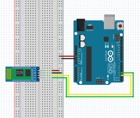
블루투스 모듈로는 HC-06을 사용하였고, 4핀으로 구성되어 있다.
블루투스 모듈의 경우 RXD, TXD 핀 이 있는데 아누이노와 연결을 할 때
RX(아두이노) - TX(블루투스센서)
RX(블루투스 센서) - TX(아두이노)
이와 같이 서로 반대로 연결을 해주어야 하는 점에 유의해야 한다.
본 실습에서는 2번핀을 RX, 3번핀을 TX로 사용할 것이기 때문에
D2(RX) - TXD(블루투스 모듈)
D3(TX) - RXD(블루투스 모듈)
로 연결하였다.
코딩은 다음과 같다.
#include <SoftwareSerial.h> //시리얼통신 라이브러리 호출

int blueRx=2;   //Rx (받는핀 설정)
int blueTx=3;   //Tx (보내는는핀 설정)
SoftwareSerial mySerial(blueRx, blueTx);  //시리얼 통신을 위한 객체선언

void setup()
{
  Serial.begin(9600);   //시리얼모니터
  mySerial.begin(9600); //블루투스 시리얼
}
void loop()
{
  if (mySerial.available()) {       //블루투스 통신이 가능할 경우
    Serial.write(mySerial.read());  //블루투스측 내용을 시리얼모니터에 출력
  }
  if (Serial.available()) {
    mySerial.write(Serial.read());  //시리얼 모니터 내용을 블루추스 측에 WRITE
  }
코딩에서 알아야 할 함수는 SoftwareSerial name(RX, TX) 이다. 아두이노의 경우 시리얼 통신포트는 0(RX)핀과 1(TX)핀으로 1대 1통신이 가능하다. 그러나 0, 1번 핀 이외에도 SoftwareSerial name(RX, TX) 함수를 통해 다른 핀을 시리얼 통신을 위한 핀으로 사용할 수 있다.
이와 같이 코딩을 구성한 후 시리얼 모니터 화면을 켜서 다음과 같이 설정해준다.
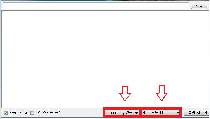
line ending 없음, 9600 보드레이트로 설정해 준다.
다음 시리얼 모니터 창에 AT 를 입력하고 OK 가 나오면 블루투스 Set-up 준비는 성공적으로 되었다.
이제 다음으로 블루투스 마스터, 슬레이브, 핀번호 추가적으로 블루투스 이름을 설정하기 위한 명령어는 다음과 같다.
-AT+ROLE=M (블루투스 모듈을 마스터로 설정)
-AT+ROLE=S (블루투스 모듈을 슬레이브로 설정)
-AT+PIN숫자 (블루투스 모듈 핀번호 설정)
-AT+NAME이름 (블루투스 모듈 이름 설정)
회로도를 보면 콘덴서와 선형 정전압기(레귤레이터)를 사용하였다.
선형 정전압기는 입력 전압이 출력 전압보다 항상 높아야 하고, 출력 전압은 사용하는 정전압기에 따라 항상 고정된 값으로 지정되는 특징을 가지고 있다. 회로도의 양쪽 끝에 있는 콘덴서를 주목하자. 이 콘덴서를 전해 (디커플링) 콘덴서라고 한다. 전해 콘덴서는 전류 내에 있는 노이즈(전압 리플)와 전력 간섭을 제거해 준다. 콘덴서의 충방전을 사용하여 인입 전압을 깨끗한 전압으로 만들어 주는 것이다.
대부분의 선형 정전압기 데이터시트에 사용 유형에 따라 이상적인 콘덴서의 값과 타입이 포함된 추천 회로가 들어 있다. 필요할 때 데이터시트를 참고하여 회로를 구성한다.
정전압기로 만든 전원과 아두이노의 전원은 서로 격리되어야 하지만, Ground는 공통으로 연결한다.
서보모터에 외부전원을 사용하는 이유?
1. 아두이노로 서보모터를 구동할 수 있지만 유도 전압 스파이크 때문에 회로가 손상될 위험이 있다.
2. 서보모터는 모터가 움직일 때 전류 소모량이 급격히 증가하는 경향이 있다. 서보모터가 특정 위치를 유지하는 동안에는 보통 아주 작은 전류를 소모하나, 서보모터가 움직이는 몇 ms 동안에는 수백 mA를 소모한다. 이런 급격한 소비 전류의 변화는 5V 전원 계통을 출렁이게 하며, 다른 부품에서 그 파동을 볼 수 있을 정도로 영향을 준다.
3. 부족한 전류로 서보모터를 구동하면 서보모터의 오동작을 초래할 수 있다.
마스터 쪽에 사용한 조이스틱의 연결은 다음과 같다.
x축 -> A0(아날로그 입출력핀)
y축 -> A1(아날로그 입출력핀)
마스터, 슬레이브 모두 디지털 입출력핀 2번을 RX, 3번을 TX로 사용하였다.
블루투스 연결이 되게 되면 사진과 같이 양쪽 블루투스의 빨간불이 깜빡이지 않고 계속해서 빛이 나온다.
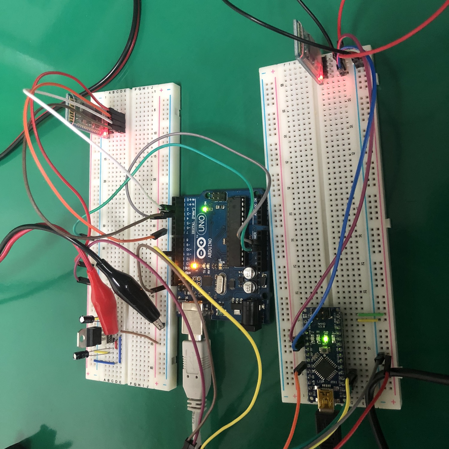
코딩은 다음과 같다.
Master
#include<SoftwareSerial.h>

int VRX = A0; //조이스틱 X축 만을 사용

int previousVRX=0; //현재 아날로그 값과 이전의 아날로그 값을 비교해주는 변수

int BLE_RX = 2;   //Rx (받는핀 설정)
int BLE_TX = 3;   //Tx (보내는핀 설정)
SoftwareSerial bleSerial(BLE_RX, BLE_TX);  //시리얼 통신을 위한 객체선언

void setup()
{
  bleSerial.begin(9600); //bleSerial 블루투스 통신
  pinMode(VRX, INPUT);
}

void loop ()
{
 int vrx = analogRead(VRX); //vrx로 조이스틱의 아날로그 값을 읽어옴
 delay(50);
 vrx = map(vrx, 0, 1023, 0, 179); //0~1023의 아날로그 범위를 서보모터 0~179 각도로 동작범위를 맵핑함
 vrx = constrain(vrx, 2, 178); //0~179 각도로 동작범위를 잡고 서보모터가 0도 까지 혹은 179도 까지 동작할 경우 떨림현상을 잡아주기 위해 실제 동작범위를 다시 2~178도로 제한

  if ((vrx <= 50) && (vrx >= 0)) //x축입력값이 50도보다 작고 0도보다 클때
  {
    if ((vrx > previousVRX+4) or (vrx < previousVRX-4)) {
      //아날로그 입력값의 1~2차이로 변동이 있을때 서보모터가 이 값을 받아 떨릴 수 있기 때문에 현재 값과 이전값을 비교하여 +4, -4 차이가 날 경우에만 아날로그 값을 블루투스로 전송
    bleSerial.write(vrx);  //x축 아날로그 값 블루투스 전송
    delay(10);
    previousVRX = vrx; // 이전값을 현재의 값으로 대치
    }
  }
  else if((vrx >= 70) && (vrx <= 177)) //x축입력값이 70도보다 작고 177도보다 클때
    {
    if ((vrx > previousVRX+4) or (vrx < previousVRX-4))
    {
    bleSerial.write(vrx);
    delay(10);
    previousVRX = vrx;
    }
   }
}
Slave
#include <SoftwareSerial.h>
#include <Servo.h>

Servo servo1;
int angle1 =90;
int vrx = 0;
#define BLE_RX (2) //Rx (받는핀 설정)
#define BLE_TX (3) //Tx (보내는핀 설정)
SoftwareSerial bleSerial(BLE_RX, BLE_TX);

void setup() {
  bleSerial.begin(9600);
  Serial.begin(9600);
  servo1.attach(11); //서보모터 11번 핀을 사용
  servo1.write(angle1); //서보모터 초기 각도 90도 설정
  }
void loop() {
  if (bleSerial.available()) { //블루투스 통신이 가능할 경우
    vrx = bleSerial.read(); //vrx에 블루투스 전송값을 전송
    servo1.write(vrx); // vrx값에 따라 서보모터 회전
    delay(10);
  }
}
동작영상은 다음과 같다.
동작 영상에서 조이스틱의 움직임에 따라 모터의 각도 값이 바뀌는 것을 확인할 수 있다. 마스터에서 조이스틱의 아날로그 값을 그대로 전송하기 때문에 서보모터의 움직임이 조이스틱을 따라가는 것을 확인할 수 있다.
감사합니다.