

라즈베리파이 GPIO 포트 ( LED, 버튼 ) 제어
1 라즈베리파이의 GPIO
아래 그림은 라즈베리파이의 GPIO 40핀 헤더의 명칭과 기능을 표시한 그림이다.
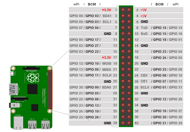
40핀헤더를 확대하여 그린 그림 좌우에 핀 번호와 제어프로그램 작성 시 사용할 명칭을 2가지로 표시해 두었다. 8번핀을 보면 ‘TxD / GPIO 14 / GPIO 15’라고 표기 해 두었다. 흑색으로 표기된 ‘GPIO 14’ 위에는 ‘BCM’ 이라고 표시했고, 회색으로 표기된 ‘GPIO 15’ 위에는 ‘wPi’라고 표시해 둔 것을 주목하자.
하나의 GPIO 핀에 대해 2가지 명칭이 있어서 혼란스러울 수 있다. 라이브러리 제작 시, GPIO핀 Naming기준이 같지 않아 발생한 현상이다.
- BCM283x 칩의 물리적인 핀 번호를 명칭에 적용한 것이 BCM으로 표시한 명칭으로, 기본 제공되는 ‘파이썬( Python )’ 라이브러리가 이 명칭을 사용한다.
- BCM283x 칩의 GPIO 핀 중 몇 번째 핀인지를 명칭에 적용한 것이 wPi로 표시한 명칭으로, Gordon이라는 사람이 만들어 배포한 C언어 라이브러리인 wiringPi 에서 사용하는 명칭이다.
- GPIO 헤더 8번핀의 ‘TxD’ 는 GPIO의 입출력 기능 외에 부가기능을 사용할 경우 시리얼 통신 포트의 ‘송신’ 기능을 사용할 수 있다는 의미이다.
2 라즈베리파이 GPIO 프로그래밍
2.0 wiringPi 라이브러리 설치
- C 언어 GPIO 라이브러리 “wringPi” 를 설치 한다. ( Python 라이브러리는 기본시스템 이미지에 포함되어 있다. )
우선, 제작자( Gordon )의 Github로부터 소스파일을 가져오기 위해 아래와 같이 명령을 입력한다.

( “drogon”은 오타 아님. 제작자 자신의 이름 “gordon” 철자의 순서를 바꾼 것임. “dragon”을 쓰려던 것이 아님. )
Git 명령 종료 후 , ‘ls’ 명령을 수행해 보면 아래 처럼 “wiringPi” 폴더가 생성된 것을 확인할 수 있다.

만약 접속이 안 될 경우 대신 GitHub를 사용하십시요.

아래와 같이 경로를 “wiringPi”로 바꾸고, “./build” 명령으로 빌드한다.

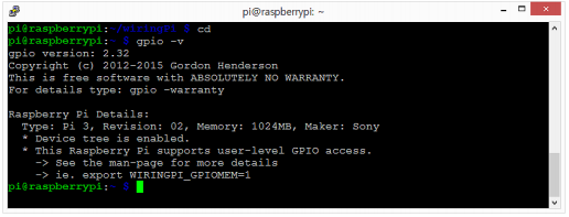
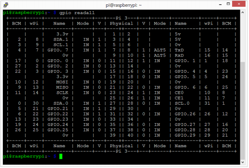
빌드가 종료되면 “gpio ?v”, “gpio readall”등을 실행하여 설치 및 확인할 수 있다.
2.1 GPIO 출력
1 GPIO 출력 테스트 회로 구성
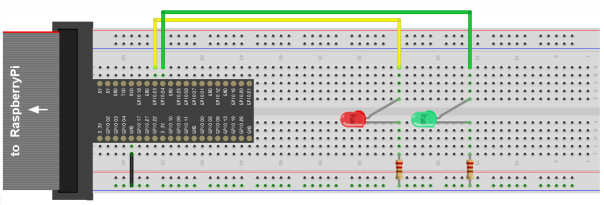
( 적색LED, 녹색LED 각 1EA, 220Ω 저항 2EA )
Red Led : GPIO 23번 연결, Green Led : GPIO 24번 연결
2. GPIO 출력 테스트 Python 코드 작성
작업폴더 생성 및 경로 변경, “nano” 편집기 실행.

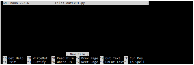
아래 코드를 “nano” 편집기를 이용하여 작성한다.
import RPi.GPIO as GPIO                    # RPi.GPIO에 정의된 기능을 GPIO명칭으로 사용
import time                                # time에 정의된 기능을 사용( time.sleep )

GPIO.setmode(GPIO.BCM)                     # GPIO 이름은 BCM 명칭 사용
GPIO.setup(23, GPIO.OUT)                   # GPIO 23 출력으로 설정
GPIO.setup(24, GPIO.OUT)                   # GPIO 24 출력으로 설정

print "GPIO Test~, press Ctrl+C to quit"   # “”메세지 화면 출력

try:                                       # try:행과 아래except KeyboardInterrupt:

  while True:                              # 무한 반복문 - C언어의 while(1)에 해당

     GPIO.output(23, True )                # GPIO 23에 HIGH 출력( 적색 LED 점등 )
     GPIO.output(24, True )                # GPIO 24에 HIGH 출력( 녹색 LED 점등 )
     time.sleep(0.5)                       # 0.5초 동안 대기

     GPIO.output(23, False)                # GPIO 23에 LOW 출력( 적색 LED 소등 )
     GPIO.output(24, False)                # GPIO 24에 LOW 출력( 녹색 LED 소등 )
     time.sleep(0.5)                       # 0.5초 동안 대기
                                           # 여기까지while TRUE: 반복구간( 들여쓰기로 구분 )
except KeyboardInterrupt:                  # Ctrl-C 입력 발생 시
  GPIO.cleanup()                           # GPIO 관련설정 Clear
  print "bye~"                             # 프로그램 종료 메세지 화면 출력
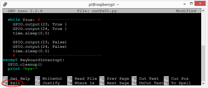
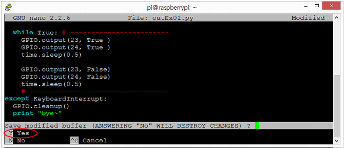
편집내용 저장 여부 선택에서 “y” 입력
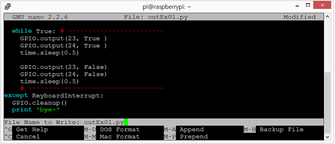
저장할 파일명 입력 단계에서 nano 편집기 실행 시 입력한 파일명을 사용할 것이므로 그대로 Enter
3. GPIO 출력 테스트 wiringPi 라이브러리를 이용한 C 코드 작성
앞서 만들어 둔 작업 폴더에서 “nano”에디터를 이용하여 “outEx01.c” 편집

아래의 코드 작성, 저장
#include <stdio.h>                           // stdio.h 파일 포함
#include <wiringPi.h>                        // wiringPi.h 파일 포함

#define LED1 4                               // 4번핀(GPIO 23) 대신 LED1사용을 위한 정의
#define LED2 5                               // 5번핀(GPIO 24) 대신 LED2사용을 위한 정의

int main (void)
{
    printf("Control GPIO by wiringPi\n");    // 메시지 화면 출력

    wiringPiSetup();                         // wiringPi 라이브러리 설정

    pinMode(LED1, OUTPUT);                   // 4번핀(GPIO 23) 출력 설정
    pinMode(LED2, OUTPUT);                   // 5번핀(GPIO 24) 출력 설정

    while(1)                                 // 무한 반복 구간
    {
       digitalWrite(LED1, 1);                // 4번핀(GPIO 23) HIGH 출력( 적색 LED 점등 )
       digitalWrite(LED2, 1);                // 5번핀(GPIO 24) HIGH 출력( 녹색 LED 점등 )
       delay(500);                           // 500ms (0.5초) 동안 대기
       digitalWrite(LED1, 0);                // 4번핀(GPIO 23) LOW  출력( 적색 LED 소등 )
       digitalWrite(LED2, 0);                // 5번핀(GPIO 24) LOW  출력( 녹색 LED 소등 )
       delay(500);                           // 500ms (0.5초) 동안 대기
    }

    return 0;
}
작성한 코드 컴파일 및 실행코드 생성

- 에러 발생 시 화면의 메세지를 참조하여 코드 수정 후 재 실행
- 위 구문에서 “outEx01”은 새로 만들어질 실행 파일명을 정해 준 것이고, “outEx01.c”는 컴파일 대상 소스파일이다.
- “-l wiringPi”는 컴파일 시, “wiringPi” 라이브러리를 이용하여 컴파일하라는 의미이다.
컴파일 결과 확인

- “ls” 명령으로 “outEx01” 실행파일이 생성된 것을 확인할 수 있다.
코드 실행

- 적색, 녹색 LED가 0.5초 간격으로 점멸하는 것을 확인한다.
- 실행 중인 코드 종료를 위해Ctrl-C 입력
2.2 GPIO 입력
1. GPIO 입력 테스트 회로 구성
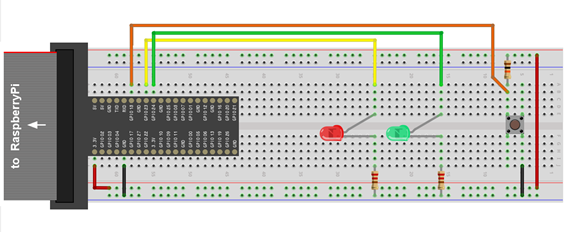
( 적색LED, 녹색LED 각 1EA, 220Ω 저항 2EA, 10kΩ 저항 1EA, SW 1EA )
Red Led : GPIO 23번 연결, Green Led : GPIO 24번 연결, 버튼 GPIO 18번 연결
2. GPIO 입력 테스트 Python 코드 작성
앞서 만들어 둔 작업 폴더에서 “nano”에디터를 이용하여 “inEx01.py” 편집

아래의 코드 작성, 저장
import RPi.GPIO as GPIO                   # RPi.GPIO에 정의된 기능을 GPIO 명칭으로 사용

GPIO.setmode( GPIO.BCM )                  # GPIO 이름은 BCM 명칭 사용
GPIO.setup(23, GPIO.OUT)                  # GPIO 23 출력으로 설정
GPIO.setup(24, GPIO.OUT)                  # GPIO 24 출력으로 설정
GPIO.setup(18, GPIO.IN )                  # GPIO 18 입력으로 설정

print "Press SW or input Ctrl+C to quit"  # 메세지 화면 출력

try:                                      # try:행과 아래 except KeyboardInterrupt:
                                          # 이하는 생략가능( GPIO warnning 방지 )
    while True:                           # 무한 반복문 - C언어의 while(1)에 해당
        GPIO.output(23, False)            # GPIO 23에 LOW 출력( 적색 LED 소등 )
        GPIO.output(24, False)            # GPIO 24에 LOW 출력( 녹색 LED 소등 )

        while GPIO.input(18) == 0:        # SW가 ON 인 동안 반복
            GPIO.output(23, True)         # GPIO 23에 HIGH 출력( 적색 LED 점등 )
            GPIO.output(24, True)         # GPIO 24에 HIGH 출력( 녹색 LED 점등 )

except KeyboardInterrupt:                 # Ctrl-C 입력 시
    GPIO.cleanup()                        # GPIO 관련설정 Clear
    print "bye~"                          # 프로그램 종료 메세지 화면 출력
아래와 같이 입력하여 작성한 코드 실행

- 스위치를 누르고 있는 동안 LED가 점등되는 것을 확인. ( 종료는 Ctrl-C )
3. GPIO 입력 테스트 wiringPi 라이브러리를 이용한 C 코드 작성
“nano”에디터를 이용하여 “inEx01.c” 편집

아래의 코드 작성, 저장
#include <stdio.h>                        // stdio.h 파일 포함( printf() 사용을 위해 )
#include <wiringPi.h>                     // wiringPi.h 파일 포함

#define SW   1                            // 1번핀(GPIO 18) 대신 SW  사용을 위한 정의
#define LED1 4                            // 4번핀(GPIO 23) 대신 LED1사용을 위한 정의
#define LED2 5                            // 5번핀(GPIO 24) 대신 LED2사용을 위한 정의

int main (void)
{
   printf("Control GPIO by wiringPi\n");

   wiringPiSetup();  // wiringPi 라이브러리 설정( pinMode(), digitalWrite() 등의 사용을 위해 )

   pinMode(SW  , INPUT );                 // 1번핀(GPIO 18) 입력 설정
   pinMode(LED1, OUTPUT);                 // 4번핀(GPIO 23) 출력 설정
   pinMode(LED2, OUTPUT);                 // 5번핀(GPIO 24) 출력 설정

   while(1)                               // 무한 반복 구간
   {
      digitalWrite(LED1, 0);              // 4번핀(GPIO 23) LOW  출력( 적색 LED 소등 )
      digitalWrite(LED2, 0);              // 5번핀(GPIO 24) LOW  출력( 녹색 LED 소등 )

      while( digitalRead(SW) == 0 )       // 스위치가 ON인 동안 반복구간
      {
        digitalWrite(LED1, 1);            // 4번핀(GPIO 23) HIGH 출력( 적색 LED 점등 )
        digitalWrite(LED2, 1);            // 5번핀(GPIO 24) HIGH 출력( 녹색 LED 점등 )
      }
   }
   return 0;                              // int main()의 리턴값-의미는 없지만 문법상 필요
}
작성한 코드 컴파일 및 실행코드 생성

컴파일 결과 확인

코드 실행

- 스위치를 누르고 있는 동안 LED가 점등되는 것을 확인. ( 종료는 Ctrl-C )