

라즈베리파이 동작 감지기 ( Motion Sensor ) 제어
네오즈 · 2019-09-27 · 6
1. 동작검지기 테스트 회로 구성
동작이 감지되면 적색 Led가 동작, 아니면 녹색 Led를 동작 한다.
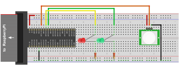
( PIR 동작 검지기 1EA, 적색LED, 녹색LED 각 1EA, 220Ω 저항 2EA )
Red Led : GPIO 23번 연결, Green Led : GPIO 24번 연결, Motion Sensor : GPIO 18번 연결
2. 동작검지기 테스트 Python 코드
코드 작성 및 실행 방법은 " 라즈베리파이 GPIO 포트 ( LED, 버튼 ) 제어 " 가이드 참조
동작이 검지되면 적색LED가, 아니면 녹색 LED가 점등되는 코드.
import RPi.GPIO as GPIO               # RPi.GPIO에 정의된 기능을 GPIO라는 명칭으로 사용

GPIO.setmode(GPIO.BCM)                # GPIO 이름은 BCM 명칭 사용

GPIO.setup(23, GPIO.OUT)              # GPIO 23 출력으로 설정
GPIO.setup(24, GPIO.OUT)              # GPIO 24 출력으로 설정
GPIO.setup(18, GPIO.IN )              # GPIO 18 입력으로 설정

GPIO.output(23, False)                # GPIO 23에 LOW  출력( 적색 LED 소등 )
GPIO.output(24, False)                # GPIO 24에 LOW  출력( 녹색 LED 소등 )

print "PIR Sensor Test"               # 메세지 화면 출력

try:                                  # try:행과 아래except KeyboardInterrupt: 이하 생략가능
    while True:                       # 무한 반복 구간 - C언어의 while(1)에 해당

        if GPIO.input(18) == 0:       # GPIO 18 입력(센서 출력)이 LOW이면
            GPIO.output(23, False)    # GPIO 23에 LOW  출력( 적색 LED 소등 )
            GPIO.output(24, True )    # GPIO 24에 HIGH 출력( 녹색 LED 점등 )

        else:                         # GPIO 18 입력(센서 출력)이 HIGH이면
            GPIO.output(23, False)    # GPIO 23에 HIGH 출력( 적색 LED 점등 )
            GPIO.output(24, True )    # GPIO 24에 LOW  출력( 녹색 LED 소등 )

except KeyboardInterrupt:             # Ctrl-C 입력 시
    GPIO.cleanup()                    # GPIO 관련설정 Clear
3. 동작검지기 테스트 C 코드
#include <stdio.h>                    // stdio.h 파일 포함( printf() 사용하기 위해 )
#include <wiringPi.h>                 // wiringPi.h 파일 포함

#define PIR  1                        // 1번핀(GPIO 18) 대신 PIR    사용을 위한 정의
#define LED1 4                        // 4번핀(GPIO 23) 대신 LED1사용을 위한 정의
#define LED2 5                        // 5번핀(GPIO 24) 대신 LED2사용을 위한 정의

int main(void)
{
     printf("PIR Sensor Test\n");     // 메시지 화면 출력

     wiringPiSetup( );                // wiringPi 라이브러리 사용설정
                                      // ( pinMode(), digitalWrite() 등의 사용을 위해 )
     pinMode(PIR,  INPUT );           // 1번핀(GPIO 18) 입력 설정
     pinMode(LED1, OUTPUT);           // 4번핀(GPIO 23) 출력 설정
     pinMode(LED2, OUTPUT);           // 5번핀(GPIO 24) 출력 설정

     while(1)                         // 무한 반복 구간
     {
        if( digitalRead(PIR) == 0 )   // 1번핀(GPIO 18) 입력이 LOW이면 - 센서출력이 LOW
        {
           digitalWrite(4, 0);        //       4(23)번핀에 LOW  출력( 적색 LED 소등 )
           digitalWrite(5, 1);        //       5(24)번핀에 HIGH 출력( 녹색 LED 점등 )
        }
        else                          // 센서 출력이 HIGH
        {
           digitalWrite(4, 1);        //       4(23)번핀에 HIGH 출력( 적색 LED 점등 )
           digitalWrite(5, 0);        //       5(24)번핀에 LOW  출력( 녹색 LED 소등 )
        }
     }

   return 0;
}
6
댓글 0개
등록된 댓글이 없습니다.