GMR 다회전 위치 센서용 마그넷 설계 방법에 대해 아나로그디바이스(ADI)의 스티븐 브래드쇼, 크리스티안 나우, 엔다 니콜에게 들어봤다.
“ADMT4000, 최초의 통합형 TPO 다회전 위치 센서”
시스템 설계 복잡성 및 개발자 수고 줄이고, 솔루션 크기·무게·비용 감소
ADI 레퍼런스 디자인 제공, 다양한 애플리케이션에서 새로운 가능성 실현
■ 트루 파워온 다회전 센서, 센싱 시장 혁신 기대
거대 자기저항(giant magnetoresistance, GMR) 센싱 기술을 기반으로 한 트루 파워온(true power-on, TPO) 다회전 센서가 산업용과 차량용 모두에서 위치 센싱 시장을 혁신할 것으로 기대된다.
기존 솔루션과 비교할 때 시스템 복잡성을 낮추고 유지보수 요구를 줄일 수 있기 때문이다.
이 글에서는 극히 까다로운 애플리케이션에서도 안정적인 동작을 보장할 수 있도록 자기 시스템(magnetic system)을 설계할 때 고려해야 할 핵심 요소들에 대해 설명한다.
또한 이 기술의 선행 개발자들이 활용할 수 있는 마그네틱 레퍼런스 디자인도 함께 소개한다.
■ 자기적 쓰기를 위해서는 특정 동작 범위 입사 자기장 유지해야
다회전 센서(multiturn sensor)는 기본적으로 자기적 쓰기 및 전자적 읽기 메모리에 통상적인 자기 각도 센서(magnetic angle sensor)를 결합하여 매우 정확한 절대 위치를 제공한다.
‘전원 중단 시에도 트루 파워온(TPO) 기능을 제공하는 다회전 위치 센서’라는 제목의 아나로그디바이스(Analog Devices)의 기술 기사에서 설명한 것처럼, 자기적 쓰기를 위해서는 특정 동작 범위의 입사 자기장을 유지해야 한다.
자기장이 너무 높거나 너무 낮으면 자기적 쓰기 오차가 발생할 수 있다. 따라서 시스템 마그넷을 신중하게 설계하고, 어떠한 표유 자기장(stray magnetic field)이 센서에 방해를 일으키지 않는지 고려해야 하며, 제품의 수명 동안 기계적 허용오차를 고려해야 한다.
낮은 수준의 표유 자기장은 측정 각도에 오차를 일으킬 수 있으며, 높은 수준의 표유 자기장은 자기적 쓰기 오차를 유발하여 총 회전 수 오차를 일으킬 수 있다.
■ 마그네틱 레퍼런스 디자인
최적의 마그넷과 차폐를 설계하기 위해서는 시스템의 요구 사항을 철저하게 이해해야 한다.
일반적으로, 시스템 요구 사항이 느슨할수록 목표 사양을 달성하기 위해서 더 크고 비싼 마그넷 솔루션을 사용해야 한다.
아나로그디바이스(ADI)는 ADMT4000 트루 파워온(TPO) 다회전 센서를 채택하고자 하는 고객들을 돕기 위해 다양한 기계적, 표유 자기장, 온도 요구를 충족하는 마그네틱 레퍼런스 디자인 시리즈를 개발하고 있다.
ADI가 개발한 첫 번째 레퍼런스 디자인은 허용오차가 비교적 느슨한 시스템을 위한 것으로서, 센서 대 마그넷 배치 2.45㎜±1㎜, 회전 축에 대한 센서의 총 변위 0.6㎜, 동작 온도 범위 -40℃∼+150℃, 표유 자기장 차폐 감쇠 90% 이상을 특징으로 한다.
■ 마그네틱 고려사항
거대 자기저항(GMR) 센서용 마그넷을 설계할 때는 다음과 같은 사항들을 핵심적으로 고려해야 한다.
○ 마그넷 소재
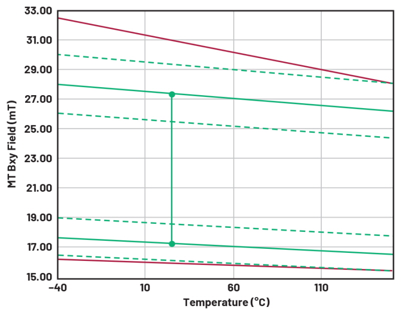
GMR 센서는 정해진 자기장 범위에서 동작한다(16mT∼31mT). 또한 그림 1의 빨간색 선에서 볼 수 있듯이, 최대 및 최소 동작 범위에 열 계수(thermal coefficient, TC)가 적용된다.
TC 값이 GMR 센서의 TC 값과 일치하는 마그넷 소재를 선택하면 작동 자기장의 허용 편차를 극대화할 수 있다. 그러면 마그넷 세기에 있어서나 센서와 관련한 마그넷 배치 허용오차에 있어서나 더 큰 편차를 허용할 수 있다.
페라이트 같은 저가의 마그네틱 소재는 GMR보다 TC가 훨씬 높기 때문에 사마륨-코발트(SmCo)나 네오디뮴-철-보론(NeFeB) 같은 소재들에 비해 동작 온도 범위를 제한할 수 있다.
선택한 마그네틱 소재의 TC와 제조 변동성으로 인한 자기장 세기에 있어서 편차를 알면 실온(25℃)에서 필요한 자기장 세기를 계산할 수 있다.
그런 다음에는 시스템이 전체 온도 범위에 걸쳐서 예상대로 동작할 것이라는 확신을 가지고 해당 설계를 실온에서 시뮬레이션할 수 있다.
그림 1에서 녹색 실선들은 GMR 센서의 활성 영역에 걸쳐서 마그넷이 발생해야 하는 자기장 세기의 범위를 나타낸다.
마그네틱 소재의 제조 프로세스 변동성 때문에, 이 범위는 GMR 센서의 최대 및 최소 동작 범위보다 낮아진다.
녹색 점선들은 통상적인 제조 변동성이 5% 이상이라고 했을 때 최소 및 최대 예상 자기장을 보여준다.

▲그림 1. 동작 범위 대 통상적인 SmCo 마그넷의 열 계수(TC) 비교
○ 마그넷 시뮬레이션
기계적 동작 환경에서의 마그넷 시뮬레이션은 다른 형태를 가질 수 있다. 마그넷을 설계할 때는 두 가지 유형의 시뮬레이션을 주로 사용한다.
해석적 시뮬레이션(analytic simulation)과 유한 요소 분석(finite element analysis, FEA)이 그것이다.
해석적 시뮬레이션은, 일반 환경에서 작동하는 것으로 간주하는 것을 제외하면, 주변 상황을 고려하지 않고 시뮬레이션하고자 하는 마그넷의 벌크 파라미터(크기, 소재)를 사용해서 자기장을 계산한다.
이 시뮬레이션은 빠른 계산이 가능하고, 강자성 물질이 가까이에 없을 때 유용하다. FEA는 더 큰 규모의 마그네틱 시스템에서 철 소재의 영향을 모델링할 수 있어서, 마그넷을 표유 자기장 차폐와 결합하거나 또는 마그넷이나 센서 가까이에 있는 강자성 소재와 결합할 때 이 방법이 필요하다.
FEA는 시간이 걸리는 작업이라, 일반적으로 이 분야에서는 해석적 분석으로부터 얻은 기본적인 마그넷 설계를 출발점으로 삼는다. 이 레퍼런스 디자인의 경우, 마그넷과 표유 자기장 차폐에 대한 시뮬레이션을 위해 FEA를 사용했다.
○ 마그넷 설계 특징
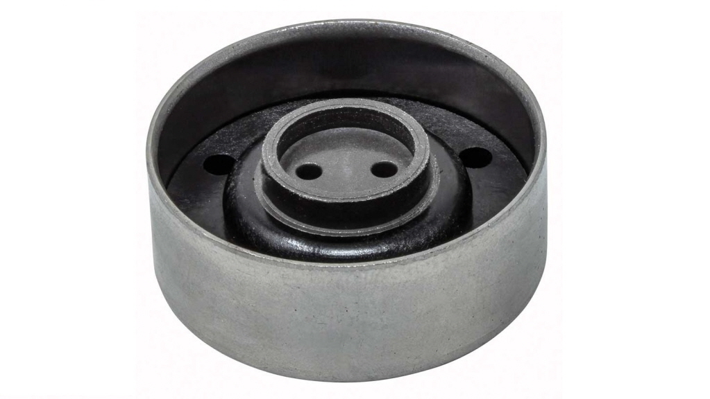
시뮬레이션 결과를 통해 얻은 이 레퍼런스 디자인 마그넷은 강철 표유 자기장 차폐와 통합된 SmCo 마그넷으로 구성된다(그림 2). 이 마그넷은 사출 성형을 하도록 설계되었기 때문에 대량 제조가 가능하다.
SmCo 마그넷의 사출 성형을 많이 사용하는 이유는, 사출 성형이 복합적인 형태를 제조할 수 있고 차량용 및 산업용 애플리케이션에 널리 사용되기 때문이다.
이 어셈블리는 9㎜ 직경의 샤프트를 사용해서 끼워 맞출 수 있도록 설계됐으나, 부싱(bushing)을 변경하면 다른 크기의 샤프트에도 부착할 수 있다.

▲그림 2. 레퍼런스 디자인 마그넷
GMR 센서용으로 견고한 마그넷 솔루션인지 확인하기 위해 이 마그넷 어셈블리에 대해 꼼꼼하게 특성 분석을 실시했다.
특성 분석의 핵심은 통제된 환경에서 확장된 마그넷 대 센서 탑재 범위에 걸쳐서 상세한 자기장 세기 맵을 작성하는 것이다.
성공적인 특성 분석을 위해서는 사용되는 자기장 프로브를 이해하고 캘리브레이션을 잘 해야 한다.
그림 3은 서로 다른 두 가지 에어 갭으로 측정된 자기장 세기를 보여준다.
전체적인 동작 온도 범위 및 에어 갭 범위에 걸쳐서 이 측정을 반복하는 데에는 다소 시간이 걸리지만, 마그넷 성능을 이해하고 요구되는 조건에서 잘 작동하는지 확인하기 위해서는 이 측정이 반드시 필요하다.

▲그림 3. 1.42㎜ 및 2.45㎜ 에어 갭을 갖는 자기장 분포
요컨대 이 레퍼런스 디자인 마그넷은 -40℃∼+150℃의 온도, 2.45㎜±1㎜ 에어 갭, 축 대 센서 배치 허용오차 0.6㎜의 동작 요구를 충족하는 것으로 확인됐다.
ADMT4000은 최초의 통합형 TPO 다회전 위치 센서로서, 시스템 설계 복잡성과 개발자의 수고를 크게 줄이고, 궁극적으로는 솔루션 크기와 무게를 줄이고 비용을 낮추도록 할 것이다.
또한 ADI는 레퍼런스 디자인을 제공함으로써 설계 엔지니어가 자기 설계 전문성을 갖췄든 그렇지 않든 상관없이 현재의 애플리케이션에서 새로운 기능이나 향상된 기능을 추가하고 다양한 애플리케이션에서 새로운 가능성을 실현하도록 도울 것이다.
ADMT4000과 마그넷 레퍼런스 디자인에 관한 더 자세한 정보는 analog.com에서 확인할 수 있으며, 현지 ADI 영업팀에 문의하여 고객 애플리케이션에 관한 조언을 받을 수도 있다.
###
※ 저자 소개
- 스티븐 브래드쇼(Stephen Bradshaw)는 리즈 대학에서 전기공학 학사학위를, 글래스고 대학에서 광전자공학 석사 및 박사학위를 취득했다. ST마이크로일렉트로닉스에서 1세대 휴대전화 카메라용 렌즈 설계와 특성분석, 마로니(Maroni)에서 Gbps 광 트랜시버, 나노테크 세미컨덕터(Nanotech Semiconductor)에서 다양한 광 트랜시버를 맡으면서 풍부한 경험을 쌓았다. ADI에서 10년 넘게 재직하고 있으며, 애플리케이션 엔지니어로서 리튬철(LiFe) 및 납축전지 배터리 모니터링 제품 라인과 자기 위치 센서를 주로 맡고 있다.
- 크리스티안 나우(Christian Nau)는 아나로그디바이스의 제품 애플리케이션 매니저로서, 차량용 전자장치와 센서를 전문으로 한다. 2015년에 FAE로서 ADI에 입사했으며 EMEA 지역의 자기 센서 지원을 담당했다. 2019년부터 ADI의 자기 센서 기술 그룹에서 일하고 있으며, 제품에 대한 고객 지원과 그룹의 미래 방향을 이끌고 있다.
- 엔다 니콜(Enda Nicholl)은 아나로그디바이스 아일랜드 리머릭의 자기 센서 전략 마케팅 매니저이다. 2006년에 ADI에 기계 엔지니어로 입사했으며, 차량용과 산업용을 비롯해서 다양한 애플리케이션 및 시장 분야에 걸쳐 센서와 센서 인터페이스 제품으로 거의 30년 넘는 경험을 쌓고 있다. 제품 애플리케이션, 필드 애플리케이션 및 영업, 전략 비즈니스 개발, 마케팅을 비롯한 다양한 직책을 거쳤다.

 ▲그림 2. 레퍼런스 디자인 마그넷