



Test Methods for Next-Generation Radar Systems: An AUDI Case Study
 Published2018.03.20 11:27
Emulation Techniques for ADAS Testing Rapidly Advancing
Starting from Lv0 warning level in 2005, ADAS stages have progressed beyond current Lv2 integrated driving assistance to reach Lv3 partial autonomous driving. In fact, German automotive company AUDI launched the A8 vehicle at the first Lv3 autonomous driving level last year, and vehicles are currently being supplied according to regional traffic regulations.
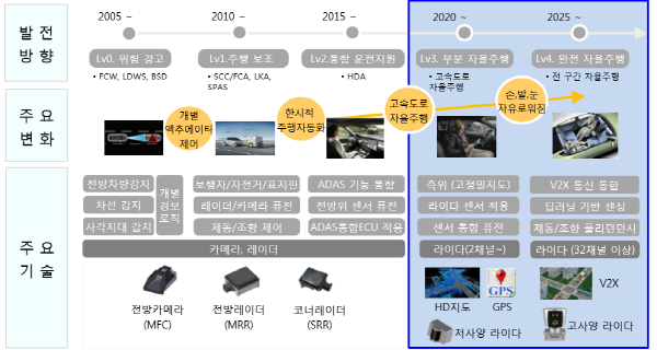
Nomura Consulting's ADAS Development Roadmap
David Hall, Senior Marketing Manager at NI, states that the development of autonomous vehicle technology is creating numerous challenges in the testing field. The radar system is one of the most readily anticipated areas.
Currently, the radar measures values and transmits them to the driver, who confirms and applies them to driving. However, in the future, the radar will be used to inform the ECU what action is needed, allowing the ECU to make decisions accordingly.
This means that from a tester's perspective, the focus shifts from simply measuring whether the radar correctly detects objects, to simulating whether object detection and the ECU's response speed and response methods are accurate.
We listened to a detailed explanation from David Hall, Senior Marketing Manager at NI, regarding methods for this comprehensive radar testing.
The focus of radar systems we currently observe has rapidly shifted from a mechanism that notifies the driver of potential problems during driving to a method that embeds more functionality within the ECU itself. In the past, the radar informed the driver of issues, but now it is evolving toward a direction where the ECU makes decisions through communication between the radar and ECU.
Radar testing aligned with this evolution of autonomous vehicles proceeds in three major approaches.
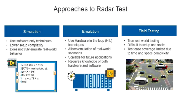
Three Basic Radar Testing Methods Proposed by NI
The first is basic simulation, which simply models radar operation using mathematical methods. This is the most fundamental approach desirable when performing engine ECU testing, where mathematical models of devices or signals can potentially be used to verify how the ECU operates in specific situations.
Another technique is to emulate the radar's own environment. This technique involves reproducing the signature of electromagnetic signals that can occur as a result of radar stimulation that bounces off objects and reflects back.
The final technique is to simply deploy radar devices in the field and conduct actual testing. This technique is very important and highly effective. However, it has the problem of requiring significant time and cost. Additionally, one of the issues encountered in field testing is the difficulty in simulating the most extreme scenarios. In reality, a radar system may operate with 99% accuracy, but the probability of not functioning correctly as intended for testing and identification is around 1% or 0.1%.
Therefore, considering the difficulty in reproducing such scenarios in field testing, it is important to use a combination of field testing and emulation to identify as many bugs as possible not only in device design but also in the device validation phase performed later.
Radar Emulation Technique: The Fastest Advancing Method in ADAS System Testing
The radar emulation concept is to reproduce the electronic signature of the environment surrounding the radar system. Regarding the operation method, a radar system using frequency modulated continuous wave (FMCW) effectively sends signals that bounce off and reflect from surrounding objects.
Once the signal bounces and reflects, the reflected signal returns to the radar system at a specific frequency and delay time according to the device's velocity and distance.
For example, if radar stimulation reflects off a rapidly moving or high-speed object, the frequency shift of the returned signal becomes more significant.
The radar system can determine both range and velocity by measuring the phase and frequency difference between the transmitted and received signals at the receiver side. There are several methods to test this capability of the radar system, and it is effective when using two different types of object simulation.
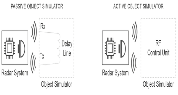
Emulation Concept to Reproduce Electromagnetic Signature of Environment Surrounding Radar System
The first is simple passive object simulation, which effectively transmits signals through delay lines. According to the distance of the delay line, the time required to propagate the signal through the actual delay line can be predicted. By applying basic physics, you can determine how long it should take to transmit the signal matching the delay line distance. Additionally, you can determine how accurate the radar system's range detection is.
Next is to use a method called active object simulation. In active object simulation, there is an object simulator or RF control unit that effectively digitalizes the signal received from the radar system. Then, using signal processing mathematically, a delay combination is applied to simulate distance. Simultaneously, frequency shift is applied to simulate the velocity or Doppler of a moving object.
When a reflected signal is generated that represents how an actual object would reflect, you can use analog-to-digital and RF converters to convert the signal back to the analog domain and retransmit it to the radar system.
Using object simulation has several advantages. First, since all objects can be modeled mathematically, multiple objects can be simulated simultaneously.
Additionally, you can simulate broader movements in terms of actual object movement and more complex scenarios accordingly. However, active simulation techniques have some issues regarding minimum distance.
This is because there are delays associated with digitalization using ADC, some signal processing, and retransmission through digital-to-analog converters. In reality, many engineers are using a combination of the two techniques.
NI Alliance Partners provide solutions that use a combination of passive and active techniques to simulate radar object behavior for radar system testing purposes.
KONRAD System Example Applied to AUDI
As can be seen in the upper right of the figure below, KONRAD creates a software package that allows users to draw device movement, and users can draw object movement relative to the radar sensor.
After loading this diagram into software and running the simulation, the object simulator reproduces the electronic signature of the device moving along that path.
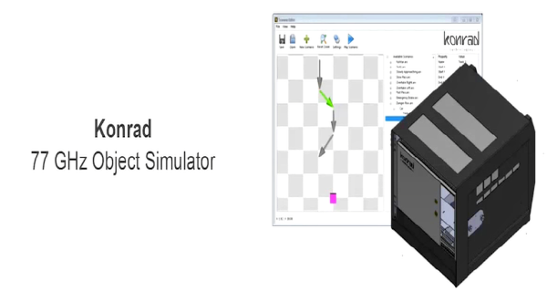
77GHz Simulator from Konrad Applied to AUDI
You can then verify that the device is operating properly by comparing the distance reported by sensor velocity with the distance of simulation velocity. One of the customers using this type of technology is AUDI.
Nils Koch, who is responsible for radar components at AUDI, mentions that the broad bandwidth of the PXI system—specifically the combination of KONRAD's software and NI's vector signal transceiver—was the ultimate factor that enabled identifying bugs using software that was previously unknown.
There are several techniques for radar testing. How these techniques are suitable for various situations, integrated vehicle testing, or integrated system testing can be explained in the figure below.
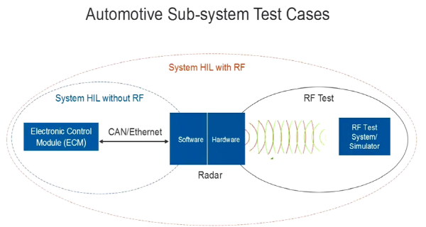
Various Radar Testing Techniques
Through this radar test simulator concept, what has just been described is actually hardware testing of the actual radar device, and potentially embedded software testing.
This radar device is used together with an Engine Control Module (ECM) or Engine Control Unit (ECU). Therefore, the ECU and radar system are interconnected. Historically, engineers have tested the ECU and ECM using Hardware-In-The-Loop (HIL) techniques across a wide range of scenarios.
Today, one of the benefits of applying techniques such as PXI's radar target emulation is that some techniques can be combined with common HIL test systems. And it means that in the past, engineers could test the ECU in a simple manner by modeling the I/O they would use and replacing that I/O with a test system capable of scenario reproduction.
Today, the advantages of PXI for HIL simulation include the fact that with PXI, you can simulate not only ECU load and open/short circuit operation but also some of the RF characteristics and synchronize the signals accordingly.
This means you can test the entire ECU or ECM through the entire RF and bus interface simulated using PXI. In fact, the ideal scenario is to test the operation of multiple interconnected ECUs, and such scenarios can be reused with HIL and PXI.
NI is currently releasing solutions that can reduce the cost and time of automotive testing and secure high-level measurement accuracy. Additionally, through NI's platform-based approach, the company provides flexible and forward-looking systems with overall timing and synchronization capabilities for the entire system, capable of meeting complex automotive test requirements including ADAS, V2X, infotainment, powertrain, body, and chassis.

Related news

Seminar Showcasing 'A to Z' of Autonomous Vehicle Technology Held
Seminar Hub held a seminar on June 14th (Wednesday) on the technology trends and future response strategies for autonomous vehicles in accordance with the Fourth Industrial Revolution. The event, sponsored by Autovein and ICN, ran from morning through afternoon. In the morning session, presentations were made on ▲value chain analysis and market analysis of core component technologies for autonomous vehicles ▲government policies and R&D status ▲ADAS development trends ▲5G communication technology trends. Park In-woo, an analyst at automotive parts/autonomous driving, who gave the first presentation, explained the overall market from the concept of autonomous vehicles, technology composition, core technologies (radar/lidar/camera sensors, recording devices, V2X communication, precision maps, actuators, IVN-based integrated DCU, etc.), to business models. Dr. Shin Jae-gon from the Automobile Safety Research Institute of the Korea Transportation Safety Authority introduced the ongoing projects, stating, "The concern of whether we can reduce traffic fatality caused by driver responsibility has expanded into policies for strengthening vehicle safety standards and applying advanced safety devices."
2017.06.16by 김자영 기자
.jpg)
NI and Shanghai University Collaborate to Develop a 5G Ultra-Reliable, Low-Latency Testbed for V2X Applications
National Instruments announced that it will collaborate with Shanghai University in China to develop a testbed focused on 5G ultra-reliable low-latency communication (URLLC) for V2X applications. Implementing autonomous driving applications requires vehicular networks with very short latency along with high reliability. Given such conflicting technical requirements and the unpredictable nature of mobile wireless channels, a 'real-time experimental testbed' capable of prototyping ideas is critical for successful research. The testbed to be developed through this collaboration will be built based on NI's flexible Software Defined Radio (SDR) hardware and 5G NR (New Radio) URLLC reference design.
2018.02.27by 김지혜 기자

NI Showcases Sensor Fusion Test Technology for Autonomous Vehicles at Automotive Testing Expo
National Instruments announced that it will participate in the 'Automotive Testing Expo 2018' to be held at KINTEX in Ilsan for four days from March 13 to 15, and will showcase the latest solutions and demonstrations including sensor fusion test technology for autonomous vehicle testing and vehicle simulators. At this exhibition, NI will publicly disclose a variety of solutions that can reduce the cost and time of automotive testing and secure industry-leading measurement accuracy. As vehicle systems become increasingly sophisticated, NI continuously develops technologies that meet more stringent test requirements to ensure system safety and quality. NI's platform-based approach provides flexible and future-oriented systems with timing and synchronization capabilities across the entire system, thereby meeting complex automotive test requirements such as ADAS, V2X, infotainment, powertrain, body and chassis.
2018.03.12by 김지혜 기자

A single misaligned light means 'defect'… Vehicle interior lighting now guarded by semiconductors and software
Automotive interior lighting is moving beyond its role as 'auxiliary lighting.' As it becomes a core element of user experience (UX) that expresses brand identity through color and animation while reflecting driver preferences, the LED interior ambient lighting market is growing rapidly. In connection with this, we met in advance with Choi Young-jae, Research Director at Dabo Corporation, who will present a technical webinar session on "Intelligent LED Interior Lighting Solutions Illuminating Future Vehicles," to hear about market trends and changes in design requirements.
2026.08.28by 명세환 기자
TI Unveils Multi-Axis Coreless Current Sensor TMCS2100-Q1 for HEV/EV Traction Inverters
Texas Instruments has unveiled the TMCS2100-Q1, a multi-axis coreless Hall-effect current sensor for HEV and EV traction inverters. By simultaneously measuring horizontal and vertical magnetic fields through multi-axis sensing technology, it achieves up to 20 times higher accuracy compared to conventional single-axis sensors, while the busbar-unmodified design provides mechanical design flexibility. It simultaneously meets the high-accuracy requirements and miniaturization driven by the expansion of 800V architectures.
2026.08.27by 배종인 기자











