



iMachine's "Beginner's Electronic Circuits, Part 2" - Understanding Electronic Circuits
 Published2018.08.13 06:44
In my case, electronic circuits feel complicated and are really difficult to approach.
While preparing and writing the previous lectures, I saw many examples of electronic circuits being compared to the movement of water.
You can think of a circuit as the process of creating a channel through which electrons (free electrons) can move.
Couldn't we call the process of arranging devices along the paths along which electrons move to perform various roles circuit design?
We set up devices here and there that perform various functions, such as widening or narrowing the waterway, installing gates, creating branching waterways to send water in different directions, and waiting in tanks.
Let's learn more through a simple circuit.
2. Super simple circuit
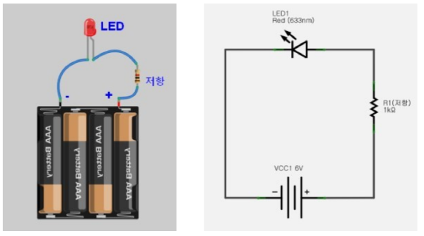
(Figure 1-1) (Figure 1-2)
[Circuit diagram 1]
Figure 1-1 is the actual shape, and 1-2 is a circuit diagram showing the same circuit symbolically.
Please familiarize yourself with the symbols for each element as they will not be explained separately in the lecture.
In [Circuit Diagram 1], the path that electrons travel is a single path.
The current has nowhere else to go, and it goes from the + pole of the battery to the - pole, passing through the resistor and the LED.
Resistance limits the current by narrowing the path.
LED is also a type of diode, a device in which electrons and holes are converted into light.
It is a simple circuit, but it can do the job of generating light.
2. Super simple+ circuit
[Circuit diagram 1] is a circuit that generates light until the batteries are completely consumed.
But if you want to make a circuit that can be turned on and off only when needed, you can add a switch.
[Circuit diagram 2] is a circuit with a switch added.
Adding a switch allows you to cut off the current.
Switches have now created circuits that can do more.
Now it can be used as a signaling device that can send signals like Morse code. ^^
It's a bit more complex circuit.
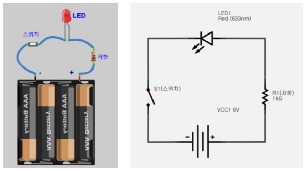
[Circuit diagram 2]
2. Super simple++ circuit
Now, if you want to send more signals, you can just add LEDs.
It's time for parallel circuits. The circuits above are circuits where components (also called elements) are connected in series.
If you connect LEDs in series, they will all turn off at once when you turn off the switch (because they are single-ended).
So this time we add a path.
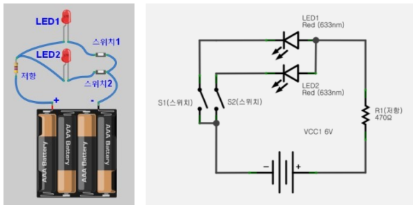
[Circuit diagram 3]
It looks a bit complicated. Now we can create more complex signals using two LEDs.
The current passes through the resistor, meets the fork in the path, is divided, and creates light as it passes through LED1 and LED2, and then passes through the switch and recombines.
You can now control the LEDs individually with Switch 1 and Switch 2.
So to speak, it became possible to express 2 bits.
In the end, wouldn't it be fair to say that even complex electronic circuits are made up of a combination of simple functions?
In the next lecture, we will learn about the famous Ohm's law and Kirchhoff's laws through simple circuit experiments.

Comments 1
1 Comments:
Related news
[PCB Trends-Part 2] Increase in high-power substrates due to increase in electric vehicles, SIP also led by automobiles
Forecasts indicate that demand for high-power substrates will increase significantly this year as demand for electric vehicles and hybrid electric vehicles continues to rise. According to the Electronic Circuit Board Industry Status Report (2017) published by the Korea Electronics Circuit Industry Association, the technology level of substrates currently in mass production continues to grow in a trend of becoming narrower, smaller, and thinner, while flexible substrates are experiencing upward leveling due to market saturation of products. With increasing high-performance specifications in smartphones and tablet PCs, the adoption of embedded substrates is growing, and build-up substrates are being used extensively in all electronic products that require miniaturization and high-speed, large-capacity data processing. Build-up substrates used as main boards in mobile devices have 8 to 12 layers with structures ranging from 1+N+1 (1 build) to 4+N+4 (4 build). The configuration is transitioning to 'stacked via,' and adoption of all layer build-up (full stacked via) structures is increasing.
2017.07.03by 김지혜 기자
[1 Minute Tech Tip]Chart Analysis of Charging Topology for Lithium Ion Cells
Efficient Charging Method Based on Charging Circuit for Wearable and IoT Applications
2018.01.02by 명세환 기자
iMachine's "Beginner's Electronic Circuit Part 1" - The 3 Elements of Electricity
Electricity can be considered an essential element of electronic circuits. From this point on, we will be serializing electronic circuit stories for complete beginners in engineering, courtesy of the so-called "iMachine" channel. Basic electronic circuit concepts that you might know or might not know—let's invest just one minute per week to learn them.
2018.07.30by 명세환 기자

Nvidia invests $5 billion in Intel
NVIDIA and Intel, leaders in global AI computing technology, are now forging ahead in providing cutting-edge solutions through NVLink-based architecture integration. NVIDIA and Intel have officially announced a strategic partnership and stated that they will jointly develop customized data center and personal computing products to accelerate diverse applications and workloads ranging from hyperscale to enterprise and consumer markets, thereby laying the foundation for the next generation computing era.
2025.09.22by 배종인 기자
.jpg)
Applied Materials Launches Environmental Protection Campaign to Mark World Cleanup Day
Applied Materials Korea (CEO Park Kwang-seon) is carrying out environmental cleanup activities with employees and their families around the Dongtan Sinricheon area on the occasion of World Cleanup Day, evolving into a company that engages with the local community beyond technological innovation.
2025.09.22by 명세환 기자












감사합니다.