



A flyback controller eliminates discrete, isolated feedback paths, simplifying design without optocouplers.
 Published2020.01.03 09:01
Consider an alternative device to the optocoupler control module.
Eliminating discrete feedback paths simplifies the solution.
Isolated flyback converters are commonly used for power conversion of approximately 60 W or less. They convert the power supply voltage into an output voltage by using a transformer with an adjustable turns ratio and a primary switch.
To maintain the output voltage as stable as possible, information about the output voltage is transmitted to the primary PWM generator through a feedback path. If the output voltage is too high or too low, the duty cycle of the PWM generator is adjusted accordingly.
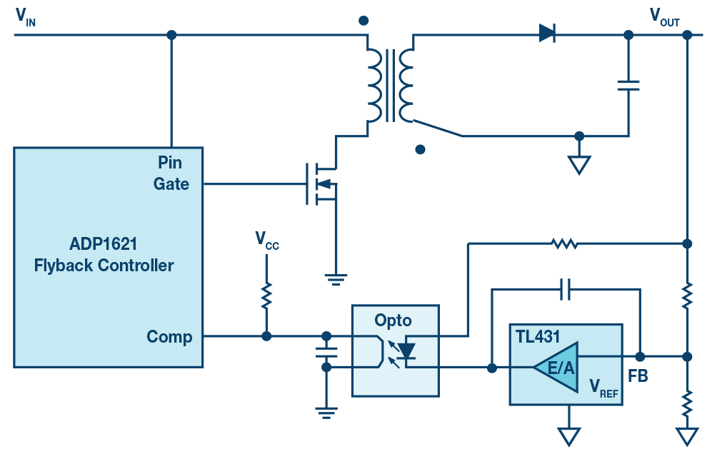
Conventional flyback controller
These feedback paths add cost, take up board space, and, along with the transformer's isolation voltage, determine the circuit's maximum isolation voltage. Optocouplers age over time, changing their characteristics, and are typically not designed to operate above 85°C.
Besides optocouplers, there are also methods to provide information about the output voltage status using transformer auxiliary windings. Here, output voltage regulation can be performed accordingly.
However, using these additional transformer windings increases the transformer cost and does not make the output voltage regulation particularly more accurate.
A better approach is to use a device that replaces the optocoupler and its secondary control module. Analog Devices' (ADI) ADuM3190 integrates iCoupler isolation technology, enabling the feedback signal to be transmitted inductively via galvanic isolation, eliminating the need for an optocoupler.
There's another way. If there's a way to completely eliminate the discrete feedback path, this would simplify the solution. Figure 2 shows a flyback converter without the discrete feedback path, such as ADI's LT8300.
This device allows you to measure the reflected voltage from the secondary to the primary, and thus determine whether and how to adjust the duty cycle produced by the PWM generator.
The advantage of this solution is that it eliminates the need for optocouplers or other feedback circuits, saving cost and space. Furthermore, it avoids the limitations of the feedback path's maximum isolation voltage. The transformer used can operate at the maximum isolation voltage within the range designed for that specific voltage.
This solution is based on the concept of boundary mode regulation, which means that the secondary current drops to 0A on each cycle. Next, the output voltage is reflected to the transformer primary winding, which is measured and used for primary side regulation.
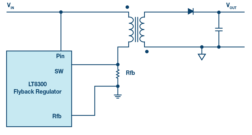
Regulating flyback controller
Whether this circuit, which eliminates the discrete feedback path, is feasible will depend on the output voltage regulation accuracy required by the application. While accuracy within ±1% can be achieved, variations may occur depending on the application.
The output voltage can be calculated using the following formula:
V OUT = 100μA × (Rfb/Nps) − Vf
Rfb is shown in Figure 2, and can be used to control the output voltage. Nps is the turns ratio of the transformer used, and Vf is the voltage drop across the secondary flyback diode. This is largely affected by temperature.
When the output voltage is high, such as 12 V or 24 V, the effect of Vf is small. When the output voltage is below 3.3 V, the effect of temperature on the output voltage becomes quite large. Some products that do not use optocouplers include a temperature compensation feature to compensate for different rectifier diode voltage drops at different temperatures.
Additionally, to maintain proper regulation, a minimal load is required at the output. For the LT8300, this is approximately 0.5% of the maximum load.
By eliminating the discrete feedback path and using a flyback controller that controls through the primary transformer winding, the design can be simplified by eliminating the error-prone optocoupler.
This article is a summary of an article titled "The Elegance of a Flyback Controller Without a Dedicated Isolated Feedback Path" by Frederik Dostal, FAE, Power Management, ADI Munich, Germany.
Comments
Related news
Silicon Labs Launches Si834x Family of Isolated Smart Switches
Silicon Labs has launched a portfolio of isolated smart switches designed to drive any load in harsh industrial environments. The Si834x product family is suitable for driving resistive and inductive loads such as solenoids, relays, and lamps used in industrial control systems including PLCs, I/O modules, relay drivers, and servo motor controllers. For safety, the Si834x product family employs CMOS-based isolation technology and provides superior reliability and performance compared to conventional optocoupler-based isolation technology, including CMTI characteristics of 100kV/μs or higher. It also supports high-side and low-side switch options, low on-resistance, continuous current up to 700mA compliant with IEC 61131-2 standard, comprehensive protection and diagnostic reporting, advanced configuration, and monitoring and control functions for industrial automation systems.
2019.08.29by 이수민 기자
ADI Unveils Dual-Drive Capability Output Driver for IIoT Applications, Boosting Power Efficiency and Reducing Electromagnetic Emissions
Analog Devices has unveiled the ADuM4122, an isolated dual-channel gate driver based on its iCoupler technology. The ADuM4122 enables designers to leverage high-efficiency power switch technology. According to the IEA, electric motor drive systems account for 40% of global electricity consumption, so improving motor efficiency can deliver significant economic and environmental benefits. The ADuM4122 allows users to switch MOSFETs or IGBTs on and off at desired speeds by providing adaptive control tailored to operating conditions, thereby controlling motor current consumption accordingly.
2019.09.19by 최인영 기자
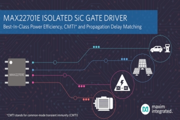
Maxim Launches MAX22701E Insulated Gate Driver
Many switch-mode power supply applications adopt wide-bandgap SiC transistors to improve power efficiency and transistor reliability. High switching frequencies induce noise-generating transient phenomena, which must be mitigated to prevent operational interruptions. The MAX22701E driver IC is used in switch-mode power supplies within industrial communication systems for high-output, high-efficiency power supplies.
2019.12.19by 이수민 기자

Intel Unveils Next-Generation 'Core Ultra Series 3' and vPro Platform for Enterprise PCs
Intel has officially unveiled the "Intel Core Ultra Series 3" for next-generation enterprise PCs and the latest vPro platform, addressing a wide range of demands from enterprise notebooks to high-performance workstations.
2026.03.26by 배종인 기자

ROHM Launches ESD Protection Diode Compatible with High-Speed Interfaces of 10Gbps or Higher
Semiconductor specialist ROHM has developed the 'RESDxVx series' of ESD (electrostatic discharge) protection diodes capable of responding to next-generation high-speed data communication environments exceeding 10Gbps, simultaneously enhancing both signal quality maintenance required in high-speed interfaces and IC protection performance.
2026.03.26by 배종인 기자











