


Dual FOC Servo Drive Solution for Robot Hands and Humanoid Robots
 Published2026.10.09 23:28
Summary
The joints and hands of humanoid robots must densely pack multiple motor axes within extremely limited space. The conventional approach of using independent drives for each axis increases board area, heat dissipation, and wiring. This white paper addresses how STMicroelectronics solves this problem through a dual servo drive solution that simultaneously performs flux-oriented control (FOC) on two axes with a single controller (STSPIN32G4). Two patented technologies—shared current sensing (US Patent US 11,757,345 B2) and junction temperature measurement with thermal distribution layout (US 12,264,976 B2)—enabled a 150 W class dual board of 4 x 4.5 cm in size. Under 40 kHz current loop conditions during dual FOC operation, MCU load reaches a maximum of 60%, with the remaining computational headroom utilized for condition monitoring and AI-based automatic tuning. The solution's nature is a reference design rather than a finished product, with applicable boundaries and limitations specified in the text.
1. Spatial Constraint Problem in Multi-Axis Drive
Designers of humanoid robots and robot hands must fit motors, reducers, and drive electronics into a space no larger than a single finger joint. In the traditional approach of using independent drive boards for each axis, current sensors, control MCUs, gate drivers, and communication circuits are replicated for every axis. This results not only in increased board area and component costs, but also accumulated heat dissipation in the confined space, potentially leading to malfunction and shortened lifespan. Therefore, the essence of the problem is not merely miniaturization, but achieving miniaturization, heat management, and reliability simultaneously.
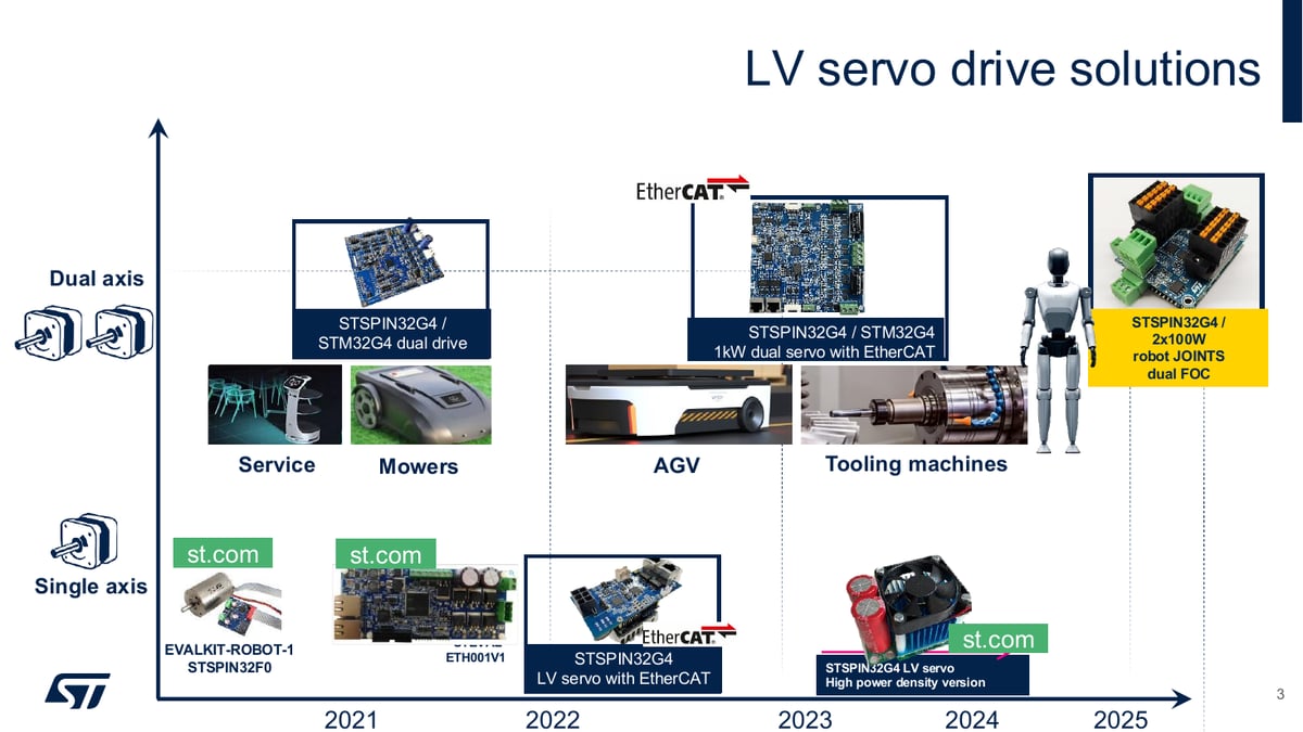
STMicroelectronics has expanded its low-voltage (LV) servo drive lineup from single-axis solutions toward dual-axis, high-power, and high-integration directions. From service robots, robotic lawnmowers, AGVs, and machine tool solutions, in 2025 a 2x100 W robot joint dual FOC solution based on STSPIN32G4 directly targeting robot joints has been added. The roadmap in Figure 1 illustrates this development. This white paper follows this latest solution, examining how the design choices address the spatial constraints described above.
2. Structure of 150 W Ultra-Compact Dual Servo Drive
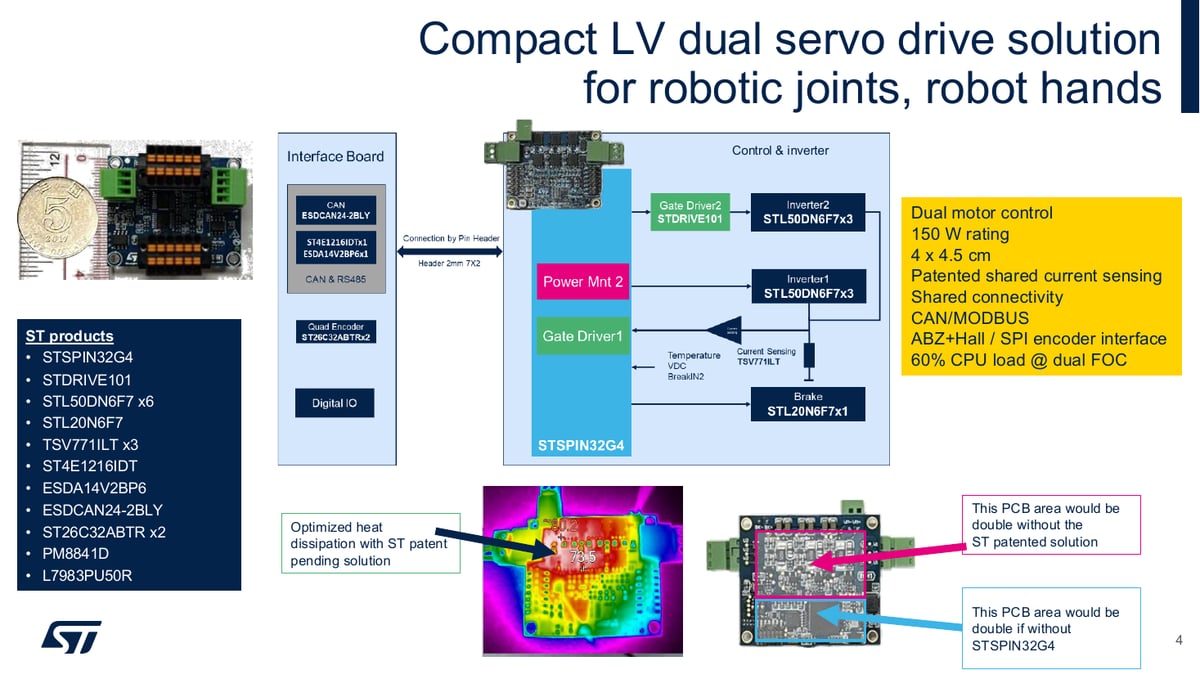
The question from the previous section leads to how to drive two axes on a single board. The small solution for robot joints controls two motors with FOC at a 150 W rated power on a single board measuring 4 x 4.5 cm. At the center of control is the STSPIN32G4, which integrates controller and gate driver, while the second inverter is managed by the STDRIVE101 gate driver. The inverter comprises six STL50DN6F7 MOSFETs, with STL20N6F7 separately placed for braking. Current signals are conditioned by TSV771ILT operational amplifiers. According to the presentation materials, without the integration degree of STSPIN32G4, the control section PCB area would have doubled, and without the patented technologies explained later, the inverter section area would also have doubled. Figure 2 shows this configuration in block diagram form.
In terms of connectivity, CAN and MODBUS are supported, with encoder interfaces accommodating ABZ and Hall sensors, as well as SPI encoders. Under conditions of driving both motors with FOC, CPU load stands at approximately 60% (detailed measurement conditions in section 5). Driving two axes in complete vector control while maintaining approximately 40% computational headroom summarizes this board's design objective. This headroom becomes the foundation for additional functions such as communication processing and predictive diagnostics.
3. Shared Sensing and Thermal Distribution Layout: Two Patented Technologies
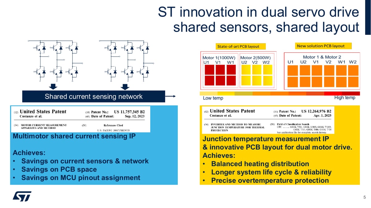
How then does the circuit for two axes fit into single-axis level area? The answer lies in two patented technologies. The first is the multi-motor shared current sensing network (US Patent US 11,757,345 B2). Conventionally, current sensors and associated circuitry that must be placed separately for each motor are designed to be shared among multiple motors. As a result, current sensors, sensing networks, PCB area, and MCU pin allocation are all reduced, making this the decisive factor enabling the 4 x 4.5 cm dual board. However, the shared structure is not without cost. According to technical Q&A, the limiting factor for current sensing is PWM duty cycle, which exists regardless of acceleration or deceleration. Therefore, motor control software (MCSDK) manages this constraint through functions that correct ADC sample timing and limit duty cycle accordingly.
The second is a patent on junction temperature measurement and PCB layout for dual motors (US 12,264,976 B2). When two motors operate together on a narrow board, heat dissipation can become uneven. This patent uses a cross-placement layout of switching devices in the two inverters to balance thermal distribution, and provides precise overheat protection through direct junction temperature measurement. As a result, system lifespan and reliability are improved. Figure 3 shows the principle of both technologies and thermal distribution differences compared to conventional layouts. In summary, the choice to share sensors, layout, and controller was the key to solving both area and heat dissipation constraints.
4. System Configuration and Reconfiguration Flexibility
Miniaturizing a single board loses value if the overall robot wiring remains complex. This solution assumes a distributed architecture where an upper motion control board issues commands to each joint's dual drive via CAN bus, with each drive managing vector control of two motors at the joint level. Since a single central controller manages multiple joints over a single bus, wiring is simplified and system expansion is straightforward when increasing joint count. According to technical Q&A, the CAN shown in the diagram is merely an example; the interface can be customized to other communication protocols such as RS-485.
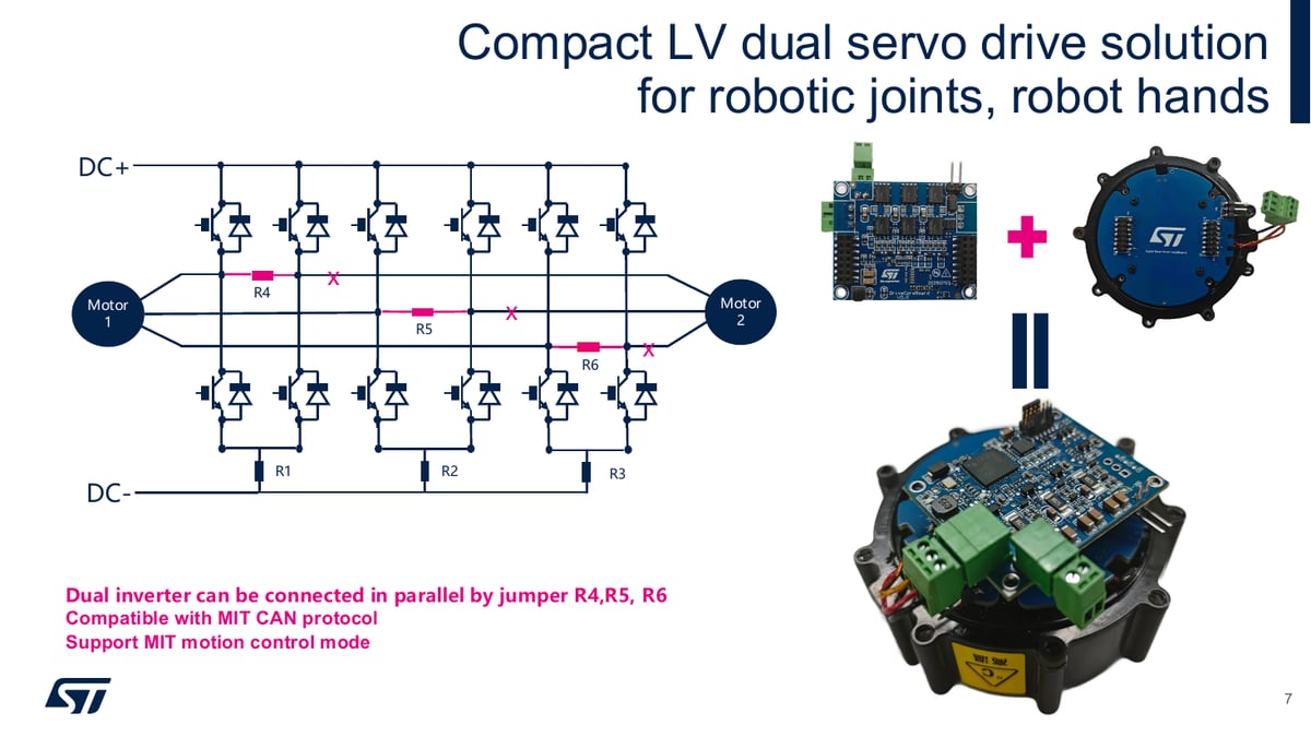
Hardware reconfiguration is also supported. Depending on application requirements, if one motor requires greater output, inverters can be paralleled via jumper resistors R4, R5, R6 to convert to a high-output single motor drive. Selection between dual drive and high-output single drive is achieved through jumpers alone, without hardware redesign. However, in parallel configuration, the capability to drive two motors independently is sacrificed, so the trade-off between axis count and power per axis must be decided at the design stage. Figure 4 shows this parallel connection structure. On the communication side, the solution is compatible with MIT CAN protocol widely used in robot actuator applications and supports MIT motion control mode, enabling adoption into existing robot control environments using that protocol without additional development.
5. Performance Verification: MCU Load, Current Loop Bandwidth, Overload Tolerance
Does the shared structure actually handle control of two axes? The first verification is MCU load measurement. Measurement results for two control configurations on the small board for robot joints are shown in Table 1. Even when increasing the current loop from 25 kHz to 40 kHz to expand control bandwidth, maximum load during dual FOC operation remains at 60%. As a result, approximately 40% computational headroom remains, providing the basis for embedding communication processing and predictive diagnostics functions on the same MCU. According to technical Q&A, 40 kHz is not the upper limit of this configuration; MCSDK settings support up to 100 kHz, but practical use is difficult due to CPU load limitations.
| Operating State | Configuration A: Current 25 kHz, Speed 10 kHz | Configuration B: Current 40 kHz, Speed 2 kHz |
|---|---|---|
| Idle | 32% | 21% |
| Single Motor Drive | 44% | 32% |
| Dual Motor Drive (Maximum) | 50% | 60% |
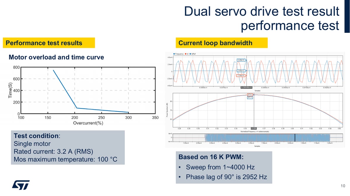
The second verification is current loop bandwidth. Based on 16 kHz PWM, frequency sweep from 1 Hz to 4000 Hz showed the frequency at which phase lag reaches 90 degrees to be 2952 Hz. This demonstrates that fast current control required for applications like robot joints, which need rapid torque response, is achievable. The third is overload tolerance. Under single motor, rated current 3.2 A (RMS), and MOSFET maximum temperature limit of 100 °C conditions, the sustainable duration curve versus overcurrent ratio was measured. A typical thermal performance curve was confirmed where shorter duration is sustained at high overcurrents and longer duration near rated current, demonstrating the thermal distribution layout of section 3 contributes to this overload tolerance. Figure 5 shows these performance test results.
6. High-Power Expansion: 2x1 kW EtherCAT Dual Servo and 3 kW Reference Design
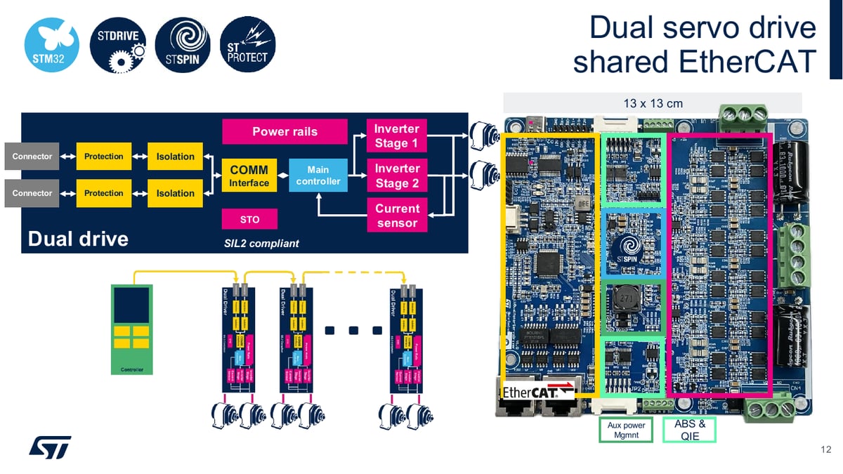
Is the same design philosophy maintained at higher power levels? The industrial dual servo drive supports 1 kW per axis, totaling 2 kW at 48 V rated, and drives two motors using the same single STSPIN32G4 and STDRIVE101 as the compact board. The rated current per axis reaches a maximum of 20 A (RMS), with the shared current sensing network patent applied identically. Both incremental and absolute encoders are supported, and communication can be selected between EtherCAT or CAN. The layout is optimized for reliability even under unbalanced load conditions where the two axes have different loads. On a 13 x 13 cm board, communication section, main control section, two inverter power sections, auxiliary power, and encoder interface are arranged by region, designed as SIL2 compliant including STO. The block diagram in Figure 6 shows this structure and daisy-chain expansion configuration. According to technical Q&A, the daisy-chain is EtherCAT-based with independent PHY at each segment, processes frames on-the-fly, has no endpoint concept, and as a result multiple joint drives can be connected in series over a single communication line, simplifying wiring.
6.1 Firmware Structure
The firmware follows a layered architecture where CiA402 drive profile and EtherCAT protocol stack are built on top of MCSDK. ST provides industrial fieldbus communication plug-ins to MCSDK to handle interworking with EtherCAT stack, and the CiA402 profile establishes itself as a unified motor drive interface. Therefore, even if the lower communication environment changes, upper application code can be maintained without modification, and developers can focus on motor control logic rather than lower-level communication integration. The plug-in includes an improved scheduler providing synchronized task timing, and encoder alignment via microshake method enables initial alignment without index signal or Hall sensor.
6.2 3 kW Single-Axis Reference Design
For cases where greater output is needed on a single axis, a reference design is also available. Supporting 3 kW with active cooling and 2 kW with passive cooling on a 8 x 5 cm board, optimized for 48 V applications. Parallel STL160N10F8 MOSFET configuration handles large current, capable of driving up to 47 A (RMS) under natural convection conditions. Current sensing uses 3-shunt differential method and supports both absolute and incremental encoders as well as Hall sensors in both differential and single-ended modes. Communication is CAN with overcurrent, overvoltage, overheat protection and regenerative braking external resistor management functions. Table 2 summarizes the positioning of the three boards.
| Item | Robot Joint Dual | EtherCAT Dual Servo | Single-Axis Reference |
|---|---|---|---|
| Axis Configuration | Dual (2x100 W class) | Dual (1 kW per axis) | Single |
| Rated Power | 150 W | Total 2 kW, 48 V | 3 kW (active cooling), 2 kW (passive cooling), 48 V |
| Board Size | 4 x 4.5 cm | 13 x 13 cm | 8 x 5 cm |
| Current Rating | Not specified | Maximum 20 A (RMS) per axis | 47 A (RMS), natural convection condition |
| Communication | CAN, MODBUS | EtherCAT or CAN | CAN |
7. Utilization of Computational Headroom: Condition Monitoring and AI-Based Automatic Tuning
The approximately 40% computational headroom confirmed in section 5 has no value by itself. Value comes from what is built on that headroom. The first application is condition monitoring and predictive diagnostics. Using Motor Pilot record function in MC-SDK v6 to log operation data, inputting it to NanoEdge AI Studio to generate anomaly detection library, then integrating alongside motor control algorithm allows motor control and anomaly detection to be performed simultaneously on the same MCU. NanoEdge AI library is available free for use on STM32G4 development boards. However, according to technical Q&A, NanoEdge AI Studio includes time-series based models but operates only within the library range provided; directly defining model structure or porting custom architectures is impossible. This differs from STM32Cube.AI, which directly converts PyTorch or TensorFlow models.
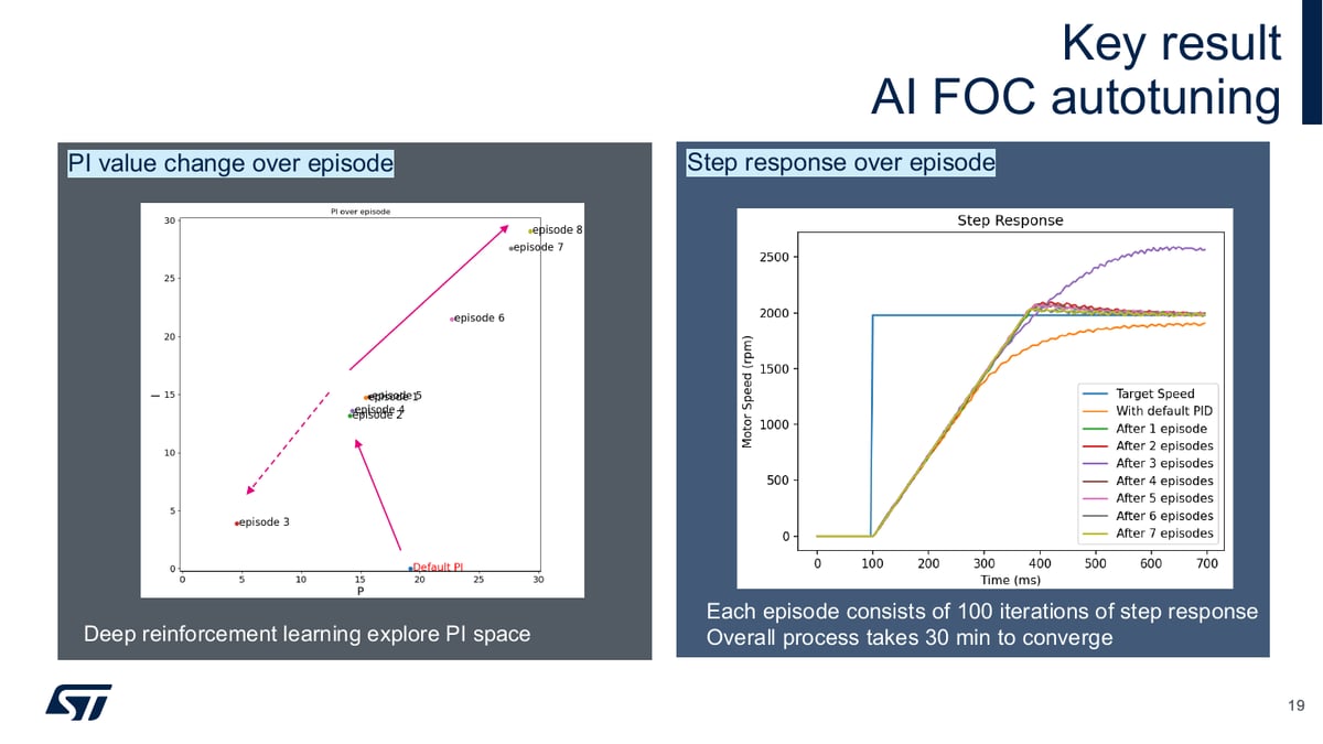
The second application is AI-based PI automatic tuning. The background involves endemic PID tuning problems. P, I, D parameters are mutually dependent, integral saturation causes overshoot, pursuit of fast response risks oscillation, while pursuit of stability causes delay. Mechanical backlash and wear, load variations demand retuning, and even motor replacement requires retuning. Therefore, ST has explored an approach delegating this iterative process to deep reinforcement learning (DRL). An agent takes the action of adjusting controller gains, receives positive reward for fast and stable response, negative reward for overshoot or oscillation, and learns good gain combinations autonomously. One episode consists of 100 repetitions of step response, and in the case presented in the presentation, the entire process converged in approximately 30 minutes. Figure 7 shows PI value convergence and step response improvement as episodes progress. As a result, without relying on tuning experience, users can find optimal PID combinations by simply setting target metrics (overshoot, settling time, etc.), and even experts save time. However, according to technical Q&A, this function was implemented through STM32Cube.AI and has not yet been officially released, requiring separate technical inquiry.
8. Application Boundaries and Limitations
Precisely understanding the nature of this solution is the starting point for application. As the presentation and technical Q&A consistently clarify, the boards presented are reference designs, not finished products. The solution does not have fixed upper and lower bounds for output and torque; rather, customization to customer specifications is assumed. ST supports hardware and firmware design related to its solutions in the customization process, but application-level coding must be performed directly by customers. Cost effectiveness also cannot be determined definitively. The inherent advantage of dual drive is simultaneous control of two axes using a single MCU and power supply, increasing system integration and synchronizing between axes; depending on system configuration, costs can actually increase.
Technical boundaries are also clear. The limiting factor for shared current sensing is PWM duty cycle, managed through MCSDK sample timing correction and duty limitation. Current control period operates stably up to 40 kHz based on STSPIN32G4 and MCSDK FOC firmware, though while 100 kHz configuration is possible, practical use is difficult due to CPU load limitations. Sensorless FOC based on ST's HSO sensorless standard can provide sufficient torque at speeds below 10 Hz depending on motor, but sensorless is rarely used in robotics requiring precision control, so development direction focuses on loss minimization and thermal optimization. AI-based PI automatic tuning is still in pre-official release stage. Additionally, development of a GaN-based robot joint solution was mentioned in Q&A but specifications remain undisclosed.
Returning to the initial tension, the problem of fitting multiple axes into narrow space has been solved by choosing to share sensors, layout, and controller instead of replicating circuits per axis. Constraints created by sharing (PWM duty cycle, sacrifice of independent drive capability in parallel configuration) are managed through firmware correction and reconfiguration flexibility, resulting in a 4 x 4.5 cm dual FOC board with 40% computational headroom, and enabling predictive diagnostics and automatic tuning on top of that headroom. This, together with the conditions designers must review when transitioning from reference to production design, represents the conclusion this white paper aims to convey.
Appendix. Webinar Technical Q&A
- Q1. Is daisy-chain connection EtherCAT or serial communication like RS-485?
- The solution is EtherCAT-based with independent PHY at each segment. Frames are processed on-the-fly as they pass through, with no endpoint concept.
- Q2. Robot hands have many drive components like motors and reducers, making power consumption a bottleneck. Is low-power design possible when applying ST solutions?
- We believe power consumption improvements are possible through thermal design IP that reduces losses. Additionally, a GaN-based robot joint solution is currently under development. Since precise control is required in robotics where sensorless is rarely used, development is focused on minimizing losses and optimizing heat dissipation.
- Q3. Are the fault diagnosis and PID tuning functions simply different applications with the same board?
- Fault diagnosis and PID tuning are merely algorithms and are not constrained by board. If you use ST MCU supported by NanoEdge AI, these can be applied.
- Q4. 1) Is the 60% MCU load at 40 kHz current control for dual motors on p.9 based on STSPIN32G4?2) To drive servo motors on the same board, is inter-controller communication via CAN?3) Are portable AI models in NanoEdge AI Studio limited? Are only NN types possible, or are time-series based models also possible?4) Is the program for tuning PID gains a function supported by ST?
- 1) Yes, measurement is based on the small solution for robot joints.2) CAN is applied in the diagram as an example; other communication interfaces like RS-485 are also available. This solution shows a configuration example as a reference, and customization is possible when actually used.3) Time-series based models are included. If there are constraints, directly defining model structure or porting custom architectures is impossible, and it operates only within the library range Studio provides. This differs from the approach of directly converting PyTorch/TensorFlow models (STM32Cube.AI), and is a tool to enable easier access to AI.4) This function was implemented through STM32Cube.AI. As it has not yet been officially released, technical inquiry with ST is needed.
- Q5. In shared current sensing method, how is current measurement accuracy maintained when two axes rapidly accelerate or decelerate simultaneously?
- Current sensing has no direct relation to rapid acceleration or deceleration. The constraint on current sensing is PWM duty cycle, which always exists regardless of acceleration or deceleration. MCSDK supports functions to correct ADC sample timing and limit duty accordingly.
- Q6. How much current interference occurs between two axes during simultaneous dual servo operation, and what methods minimize it?
- Since inverters are independent, current interference between axes is essentially negligible. This can be further minimized through PWM phase delay.
- Q7. When simultaneously performing two FOC operations in a single microcontroller, what is the processor utilization rate?
- Based on 40 kHz current control and 2 kHz speed control, approximately 60% on STSPIN32G4 running MCSDK firmware.
- Q8. To what extent can current control period be stably implemented and what is the maximum control speed?
- Based on STSPIN32G4 and MCSDK FOC firmware, 40 kHz can also be stably controlled, though this is not necessarily the maximum. In practice, motor control applications rarely exceed 40 kHz switching. MCSDK supports settings up to 100 kHz, but practical use at 100 kHz is difficult due to CPU load limitations.
- Q9. When miniaturizing circuit boards, what is the most important design factor to consider for reducing electromagnetic interference and noise?
- Loop area minimization and ground separation should be carefully considered. The larger the loop area of the path carrying high-frequency switching current, the greater the radiated noise, so minimizing the physical length and width of this path is paramount.
- Q10. In dual servo drive environments, which component generates the most heat, and are there actual cases addressing this?
- In motor control, the most heat-generating component is the switching device. This is typically resolved through appropriate heatsinks and via design.
- Q11. What methods minimize impact when switching between torque control, speed control, and position control?
- Bumpless transfer, handing off the current output value (torque, speed, position) as the initial value for the next controller at the switching point, is critical. With integrator initialization and reference ramping aligned just before switching, transitions can occur without impact.
- Q12. When applying FOC without position sensor, what level of low-speed performance can be achieved?
- Based on ST's currently distributed HSO sensorless standard, depending on the motor, sufficient torque can be provided even below 10 Hz.
- Q13. What are recommended criteria when adjusting current control and speed control to match actual equipment?
- It depends on the application. Whether to allow overshoot for faster response speed or prioritize stability without allowing any overshoot differs per application. Current controllers are generally tuned to follow within approximately 10 cycles maximum.
- Q14. What is the scope of reference design, control software, and technical support provided from development through production?
- ST provides reference solutions composed of ST products, customizable to customer requirements. During customization, hardware and firmware design related to the solution is supported, with application-level coding to be performed directly by customers.
- Q15. Compared to conventional single servo method, what actual cost savings can be achieved when applying dual servo?
- It varies depending on system configuration. Costs can actually increase in some areas, making definitive answers difficult. Inquiry through ST sales and marketing channels enables assessment tailored to the system. The advantage of dual drive is increasing system integration and synchronizing between axes through simultaneous control of two axes using a single MCU and power supply.
- Q16. For humanoid robot joints as reference, what maximum power and maximum torque can be supported?
- The solution does not have fixed performance upper and lower bounds. We provide a reference, and customization to specifications is possible.
- Q17. I'm curious about what proportion T1S control occupies in robots compared to how automotive node control stands.
- Accurate answer is difficult due to lack of information on T1S.
- Q18. Using small artificial intelligence technology, is it possible to implement AI functions without separate high-performance devices?
- NanoEdge AI also supports lower-performance MCUs. Learning and other high-performance functions are difficult to implement, but inference is possible.
- Q19. What control values does AI-based automatic adjustment function automatically set, and what improvements over existing methods are achieved?
- By setting controller objectives (overshoot, settling time, etc.), optimal PID combinations are found through automatic adjustments. The advantage is that anyone can perform tuning without relying on motor control experience, and even experienced users save time.

Comments
Related news
[Interview] Matteo Maravita, ST AICC Center Director, "We will lead the democratization of edge AI with low-power, high-efficiency embedded AI platforms"
Recently, the center of AI is shifting from cloud to edge due to fast response speed, reduced power consumption and costs, and improved security. Additionally, in embedded AI development, model optimization tailored to limited memory environments is becoming increasingly important. In this context, STMicroelectronics is actively working to reduce costs and power consumption by implementing high-performance vision and audio AI in MCU environments through the Neural-ART accelerator in STM32N6. Furthermore, through technical support and development ecosystems, the company is helping customers' AI ideas reach mass production. Against this backdrop, we met with Matteo Maravita, director of ST APAC AI Competence Center (AICC), to discuss the direction of edge AI development and ST's strategy.
2026.10.08by 배종인 기자
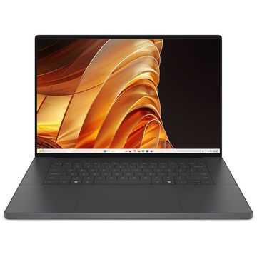
Dell Unveils 'XPS 16 Creator Edition' with RTX Spark
Dell Technologies has unveiled the premium creator notebook 'XPS 16 Creator Edition' equipped with NVIDIA RTX Spark superchip. Integrating Blackwell RTX GPU and Grace CPU on a single silicon, this product can perform heavy workloads such as large-scale AI model inference, 3D rendering, and 8K video editing in local environments without memory constraints. Scheduled for domestic launch on October 16th, it targets creators, developers, and gamers as primary users.
2026.10.08by 배종인 기자
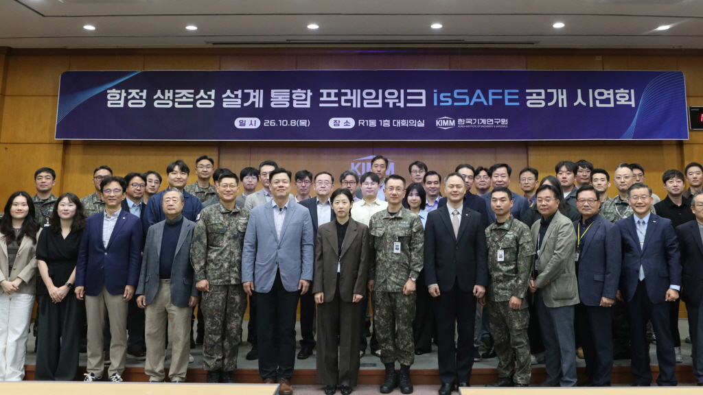
KAERI Develops Domestically-Produced SW 'isSAFE' for Integrated Warship Survivability Analysis
The Korea Institute of Machinery and Materials has developed domestically-produced software 'isSAFE' that comprehensively analyzes warship survivability. This design framework integrates the entire process—from warship modeling to hit scenario generation, vulnerability analysis, and results analysis—into a single platform, establishing an independent technology foundation in the defense technology sector that had previously relied on foreign software.
2026.10.08by 배종인 기자

DeepX and Doosan Robotics Joint Development of AI Welding Solution for Nuclear Power Plants
DeepX and Doosan Robotics are jointly developing an intelligent welding solution that combines AI, collaborative robots, and on-device NPU to address the shortage of skilled welding personnel at nuclear power plant manufacturing sites. Selected as a project under the Ministry of Trade, Industry and Energy's Robot Industry Technology Development Program, this project is being pursued as a four-party consortium with SAIGE and Changwon National University, targeting commercialization by 2030.
2026.10.06by 배종인 기자
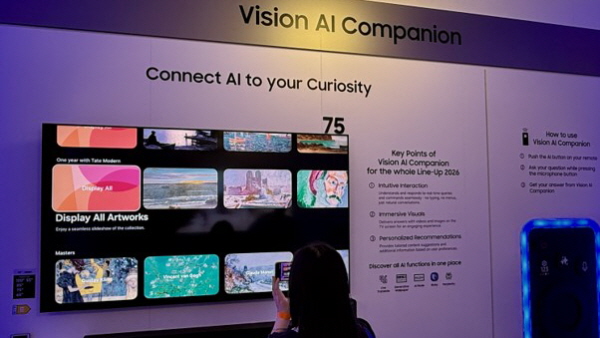
[IFA 2026 Settlement ②] AI Everywhere, Now It's About Life, Not Technology
IFA 2026 demonstrated through the 'AI Everywhere' trend that appliances have evolved to a stage where they make judgments and take actions independently. Functions that automatically determine optimal operation after recognition based on cameras and sensors, like Miele and Siemens products, have become widespread, and LG, Hisense, and Samsung presented the 'AI Companion' concept where the entire home operates as a single AI system. AI is no longer a special feature but has established itself as basic infrastructure that reduces inconvenience in daily life, and true competitiveness now depends on how much AI can make decisions on behalf of users. This can be confirmed through the second article of the IFA 2026 settlement.
2026.10.06by 김학용 기자











