



[1 Minute Tech Tip]Chart Analysis of Charging Topology for Lithium Ion Cells
 Published2018.01.02 09:47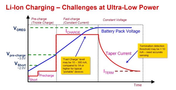
The figure above illustrates the charging topology for lithium-ion cells, with the red line representing constant current and the blue line representing constant voltage.
When the battery is under voltage, constant current is applied to the cell until the voltage reaches 4.2 V. At this point, the system switches from constant current to constant voltage. The cell voltage should not exceed 4.2 V, and the current is gradually reduced until it approaches 0, which means “I” termination. When the cell voltage reaches 4.2 V, the current stops flowing and the cell is considered fully charged.
There are also some considerations to protect against battery abuse or fault conditions. For example, if a cell is shorted or in default state, passing full current through the circuit can cause battery damage. Therefore, at low voltages, only a small test current is applied to wake up the battery in case the battery PCM (Protection Circuit Module) trips.
In the 2 V to 3 V range, a precharge current of approximately 1/10 of the rapid charge current is generally applied. This is called the precharge period, and the battery is charged by slowly flowing current like a dripping water drop.
When the cell is charged to 3V or more, it is judged to be stably charged and switches to rapid charging, and this section is called constant current. Finally, in the case of an actual battery, when the voltage reaches approximately 4.2V, it becomes a constant voltage section and the current gradually decreases.
It is also possible to terminate the charge while maintaining the current at 1/10 of the rapid charge range. At this time, termination detection must be possible at 10mA or less, and accurate sensing is essential.

Comments
Related news
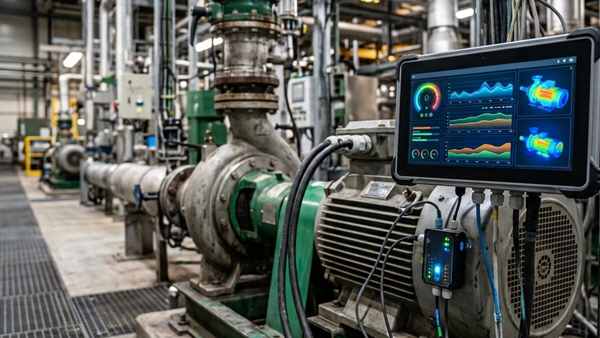
[Technical Contribution] Mouser: "AI Agents Help Accelerate and Standardize Industrial Field Maintenance Operations"
Abhishek Jadhav from Mouser Electronics discusses how to leverage agentic AI for predictive maintenance in industrial automation.
2026.10.23by 편집부
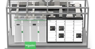
Schneider Electric Unveils Modular Power Solution for AI Data Centers
Schneider Electric has launched prefabricated power modules and power skids for AI data centers, jointly developed with NVIDIA. Based on the GB300 NVL72 reference design, the solution applies standardized design and factory pre-fabrication methods to build power infrastructure in as little as 6 months. Galaxy VXL UPS technology is integrated, with capacity options ranging from 2MW to 2.5MW.
2026.10.23by 배종인 기자

Dassault Systèmes and Vertiv Announce AI Factory Design and Construction Collaboration
Dassault Systèmes and Vertiv announced their collaboration on AI factory design and construction. By combining the virtual twin-based 3DEXPERIENCE platform with Vertiv's infrastructure solutions, the entire system is validated in a virtual environment before actual construction. Through this approach, they aim to accelerate the design process by up to 10 times and reduce infrastructure construction timelines by up to 50%.
2026.10.23by 명세환 기자
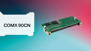
Hilscher Launches 'comX 90CN' Embedded Module Without Connector Integration
Hilscher has launched the 'comX 90CN' embedded communication module without connector integration. Designed in a compact 30×70mm form factor, this module features a structure where network connectors are separately connected to the baseboard, enabling flexible mechanical design for industrial equipment. Based on netX 90, it supports major industrial Ethernet protocols including PROFINET, EtherCAT, and EtherNet/IP, and incorporates security features such as hardware-based encryption and secure boot.
2026.10.19by 배종인 기자

Korea Institute of Machinery and Materials, Duwon University of Science and Technology, and Duwon Heavy Industries Sign MOU on Manufacturing AI Transformation Industry-Academy-Research Collaboration
The Korea Institute of Machinery and Materials has partnered with Duwon University of Science and Technology and Duwon Heavy Industries to establish an industry-academy-research collaboration system in response to AI transformation in the manufacturing sector. An industry-academy-research collaboration center will be established at the Anseong Campus, joint research in the mobility, aerospace, and defense sectors will be promoted, and specialized workforce development tailored to field demands will be pursued through the establishment of the AI Mobility Machinery Department starting in the 2027 academic year.
2026.10.19by 배종인 기자











