



Synchronous SEPIC suitable for automotive and industrial applications
 Published2019.07.26 12:05
| SEPIC, 입력 전압 달라도 다른 전원 공급
| ADI LT8711, SEPIC 가능 DC-DC 컨트롤러
동기 SEPIC 토폴로지를 지원하는 제품은 그렇게 흔치 않다.
아나로그디바이스(ADI)의 LT8711은 동기 벅, 부스트, SEPIC(Single-Ended Primary-Inductor Converter), ZETA 토폴로지와 비동기 벅-부스트 토폴로지가 가능한 DC-DC 컨트롤러다.
SEPIC 토폴로지는 입력 전압이 출력보다 훨씬 낮게 떨어지거나 출력보다 훨씬 높게 상승하더라도 안정적인 출력 전압을 제공할 수 있다는 점에서 유용하다.
콜드 크랭크나 부하 덤프가 발생될 수 있는 자동차 애플리케이션과 공장 환경에서 긴 전원 라인을 사용하고 정전이 발생될 수 있는 산업용 애플리케이션에 특히 중요하다.
석유가스 분야에 사용되는 장비는 SEPIC 컨버터를 사용해서 신뢰성을 높일 수 있다.
다중의 전원장치를 사용해서 주요 부하로 전원을 공급하면서 어느 한 전원에서 문제가 생겼을 때 입력 전압이 다름에도 불구하고 SEPIC이 다른 전원을 사용해서 부하로 전원을 공급할 수 있기 때문이다.
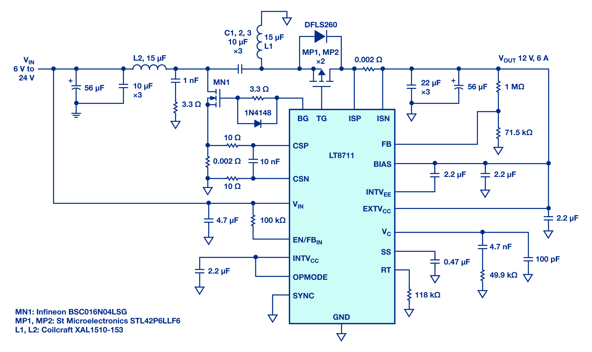
그림 1은 파워트레인 용으로 LT8711을 채택한 동기 SEPIC 컨버터로서, 다음과 같은 부품들을 사용하고 있다.
▲2개의 비결합 인덕터 L1과 L2
▲N-채널 MOSFET MN1, BG 핀을 사용해서 구동
▲2개의 동기 P채널 MOSFET MP1과 MP2, TG 핀을 사용해서 구동
▲디커플링 커패시터 C1, C2, C3
▲입력 및 출력 필터
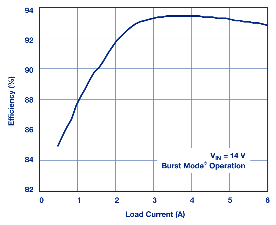
그림 2는 14V 입력 전압일 때 이 컨버터의 효율을 보여준다. 동기 방식을 사용함으로써 피크 효율이 93.4%로서 높은 효율을 달성한다.
그림 3과 그림 4는 입력 전압이 출력보다 낮게 떨어지거나 높게 상승하더라도 안정적인 출력 레귤레이션을 유지한다는 것을 보여준다.
이 디자인을 위해서 데모 회로 DC2493A의 출력 전류를 4A에서 6A로 높이도록 수정했다. 또 MOSFET MN1 및 MP1과 인덕터 L2를 그림 1에서 보는 부품들로 대체했다.
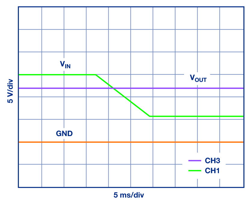
레일 전압 VIN이 15V에서 6V로 떨어지더라도
VOUT이 12V로 안정적으로 유지된다

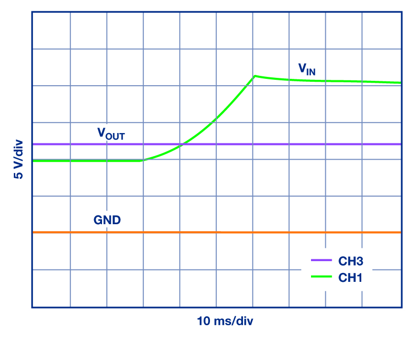
레일 전압이 10V에서 20V로 상승하더라도
VOUT이 레귤레이션을 유지한다
수정된 DC2493A 데모 회로를 사용해서 이 디자인을 평가했다.
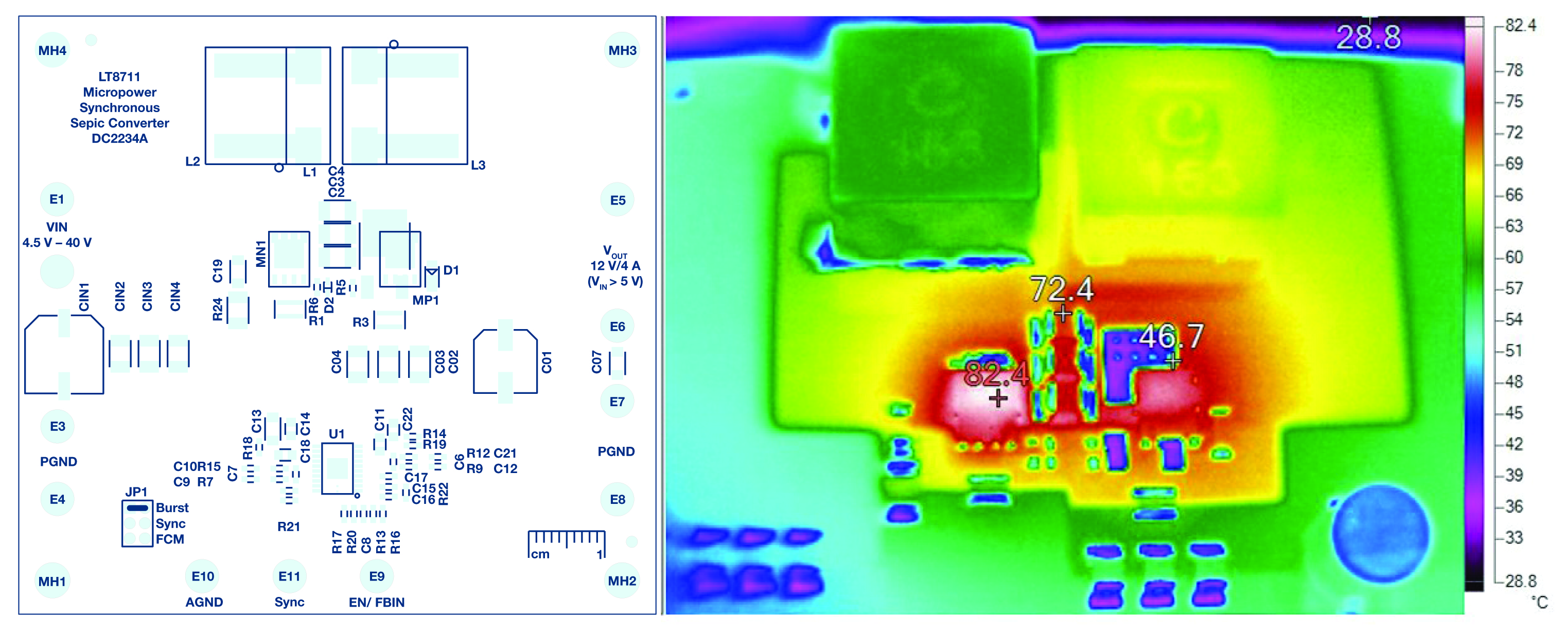
동작할 때의 열 영상(VIN14V,VOUT12V/6A)
그림 5는 이 보드의 열 영상을 보여준다.
LT8711 데모 회로는 비슷한 솔루션의 LTspice모델을 제공한다. 또 LT8711 데이터 시트에서는 SEPIC 파워트레인 부품을 어떻게 적절히 선택할 수 있는지 설명하고 있다.
다음은 이 토폴로지로 기본적인 기능을 이해할 수 있도록 피크 전압과 전류를 계산하는 공식이다.
IL1 = IIN + ΔIL1;
IL2 = IOUT + ΔIL2;
VBG = VTG = VIN + VOUT;
ITG = IBG = IIN + IOUT + ΔI/2.
LT8711은 동기 벅, 부스트, SEPIC, ZETA와 비동기 벅-부스트 컨버터가 가능하도록 설계된 범용성과 유연성이 뛰어나다.
동기 SEPIC을 사용함으로써 변동적인 입력 전압 범위에서도 높은 효율로 안정적인 출력을 제공할 수 있다. 이 점은 자동차와 산업용 애플리케이션에 중요하다.

이 기사는 아나로그디바이스의 빅터 카시예프(Victor Khasiev) 선임 애플리케이션 엔지니어의 '자동차 및 산업용으로 적합한 고효율 동기 SEPIC(High Efficiency Synchronous SEPIC for Automotive and Industrial Installations)'을 정리한 것입니다.
Comments
Related news
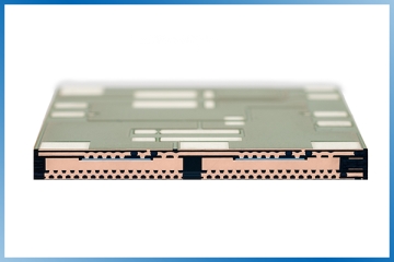
'Chip embedding technology' that embeds MOSFETs into PCBs improves performance of hybrid vehicle 48V systems
Infineon Technologies and Schweizer Electronics have developed new technology for mild hybrid vehicles. Chip embedding technology that integrates power MOSFETs into PCBs significantly improves the performance of 48V systems and reduces complexity. Continental Powertrain has decided to adopt this technology in 48V starter generators to be supplied to major European automotive manufacturers. The 48V starter generator is a key component that plays a crucial role in reducing CO2 emissions of mild hybrid vehicles by up to 15% compared to conventional drive trains.
2019.05.15by 이수민 기자
Mouser is now stocking ADI's LTM2810 μModule isolator.
Mouser Electronics announced that it is supplying Analog Devices' Power by Linear LTM2810 μModule isolator. The LTM2810 μModule isolator, which provides isolation performance of up to 7.5kVRMS, is suitable for use in inspection and measurement equipment, medical equipment, electric vehicle and hybrid electric vehicle systems, industrial applications, and instrumentation systems. The LTM2810 μModule isolator includes a separate logic supply pin to support convenient interfacing at different logic levels in the range of 1.6~5.5V.
2019.06.21by 이수민 기자
ADI-First Sensors Commit to Mass Supply of LiDAR Solutions
Analog Devices will collaborate with First Sensor AG to develop autonomous sensing products for unmanned vehicles, aerial and underwater transportation systems used across various industrial sectors including transportation, agriculture, and manufacturing. As part of this collaboration, the two companies will develop products that reduce the lidar signal chain. Through this product, manufacturers seeking to incorporate sensing and recognition technologies into autonomous safety systems will be able to achieve superior system performance while reducing system size, weight, power consumption, and cost. The two companies also plan to develop additional lidar products for automotive and industrial manufacturing applications.
2019.07.05by 이수민 기자

Intel Unveils Next-Generation 'Core Ultra Series 3' and vPro Platform for Enterprise PCs
Intel has officially unveiled the "Intel Core Ultra Series 3" for next-generation enterprise PCs and the latest vPro platform, addressing a wide range of demands from enterprise notebooks to high-performance workstations.
2026.03.26by 배종인 기자

ROHM Launches ESD Protection Diode Compatible with High-Speed Interfaces of 10Gbps or Higher
Semiconductor specialist ROHM has developed the 'RESDxVx series' of ESD (electrostatic discharge) protection diodes capable of responding to next-generation high-speed data communication environments exceeding 10Gbps, simultaneously enhancing both signal quality maintenance required in high-speed interfaces and IC protection performance.
2026.03.26by 배종인 기자











