


eGaN FETs for LiDAR - Getting the Most Out of Laser Drivers Theory
 Published2019.09.09 19:27
지난 몇 년 동안 한 가지 형태의 특정 라이다인 TOF(Time-of-Flight) 거리 측정이 널리 사용되어 왔다. 레이저가 광학 소스로 사용되면, 먼 거리에 있는 작은 부분까지의 거리도 측정할 수 있으며, 조정 가능한 광학장치와 함께 사용하면, 해당 지점까지의 거리를 측정하고, 객체의 3차원 맵을 구현할 수 있다.
EPC는 라이다 시스템에 eGaN FET의 성능을 제공하고, 라이다의 기술 수준을 향상시키기 위해 EPC9126 및 EPC9126HC 레이저 드라이버를 개발했다.
이 레이저 드라이버의 기본 원리는 간단해 보이지만, 많은 엔지니어들이 설계에서 무시하는 기생 컴포넌트들이 고속, 고전압, 고전류 특성을 갖게 한다.
본 기술 기고문은 사용자가 드라이버를 최대한 활용할 수 있도록 레이저 드라이버 디자인에 대한 심도 깊은 정보를 제공하고, 일반적으로 제기되는 질문에 답을 제시하기 위해 작성되었다.

그림 1 ┃기본적인 라이다 시스템
레이저 및 펄스 요구사항
TOF 라이다는 일반적으로 근적외선(NIR: Near-Infrared) 반도체 레이저 다이오드와 측면 발광 에피택셜 레이저나 또는 VCSEL(Vertical Cavity Surface Emitting Laser)을 사용한다.
일부 일반적인 레이저 다이오드는 그림 2 에 나와 있다. 레이저 다이오드는 전기적으로 정류기 역할을 수행한다. 특정 임계 전류 이상으로 순방향 바이어스되면, 순방향 전류와 대략적으로 비례하는 출력 광 전력으로 레이저 방사선을 방출한다.
따라서 전류 펄스로 이를 구동하면, 레이저 광 펄스를 얻을 수 있다. 레이저 광 펄스는 펄스폭과 에너지의 두 가지 주요 파라미터를 가지고 있으며, 이 두 가지 요소는 각각 거리 분해능과 범위에 큰 영향을 미친다.
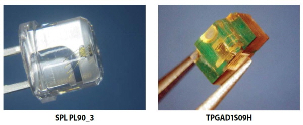
그림 2 ┃TOF 라이다에 사용되는 일부 일반적인 레이저 다이오드
전송된 광 신호의 펄스폭은 라이다 시스템의 거리 분해능에 상당한 영향을 미친다. 그림 1 은 이러한 케이스를 보여주고 있다.
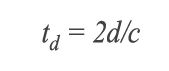
상단의 케이스를 보면, 라이다에서 좁은 펄스의 광을 내보낸다. 이 광펄스가 목표물로 이동하고, 반사되어 다시 돌아와야 하기 때문에 거리 d에서 목표물에 대한 펄스의 송신과 수신간의 시간 td는 다음과 같다:
펄스 길이가 너무 길어지면, 반사되는 펄스와 겹치기 시작하며, 환경에서 특성을 구별하는 것이 어려워진다. 실제로 어떤 길이의 펄스가 바람직한지에 대한 아이디어를 얻기 위해 레이저 다이오드를 구동하는 1ns의 전류 펄스폭을 고려해 보도록 하자.
이는 30cm의 광 펄스 길이에 해당한다. 목표물의 특성과 15cm 거리에 이르게 되면, 수신되는 펄스와 겹치기 시작하고, 구별이 더 어려워진다. 다양한 신호처리 기법을 통해 주어진 펄스폭에 대한 분해능을 향상시킬 수는 있지만, 기본적으로 더 짧은 펄스가 더 뛰어난 정밀도를 제공하고, 수나노초 또는 그 이하의 펄스가 인간적 척도에 부합하는 분해능으로 바람직하다는 것은 분명한 사실이다.
펄스 에너지는 라이다의 범위를 결정한다. 보다 뛰어난 분해능에 대한 요구로 인해 펄스폭을 더 좁게 설계하고 있기 때문에 충분한 펄스 에너지를 유지할 수 있도록 다이오드 전류가 증가해야 한다. 일반적인 펄스 전류는 수암페어에서 수백 암페어에 이를 수 있다.
다수의 레이저 다이오드는 수십 암페어 범위의 공칭 펄스 전류를 가지고 있다. 예를 들어, 일반적인 데이터 시트 테스트 조건, 즉 PRF(Pulse Repetition Frequency) = 1kHz, 펄스폭 tw = 100ns, 피크 전류 IDLpk = 30A, 동작 온도 TOP = 23 ~ 25°C의 경우, 최대 전기 입력 전력은 삼중접합(Triple Junction) 에지 방출 레이저의 경우 300W에 이를 수 있다.
평균 테스트 듀티 사이클은 레이저 다이의 과열을 방지하기 위해 종종 ≤0.1%이다. 이는 레이저 다이오드를 더 높은 전류에서 더 짧은 펄스폭으로 동작시키고, 더 뛰어난 피크 광 출력을 얻을 수 있다.
요약하면, 라이다 시스템에 적합한 상용 레이저 다이오드에 대한 일반적인 레이저 다이오드 요구사항은 1ns ~ 10ns에 이르는 펄스폭과 수 암페어에서 수백 암페어의 피크 펄스 전류를 필요로 한다. 다음 섹션에서는 이러한 극단적인 펄스를 얻는 방법을 살펴보겠다.
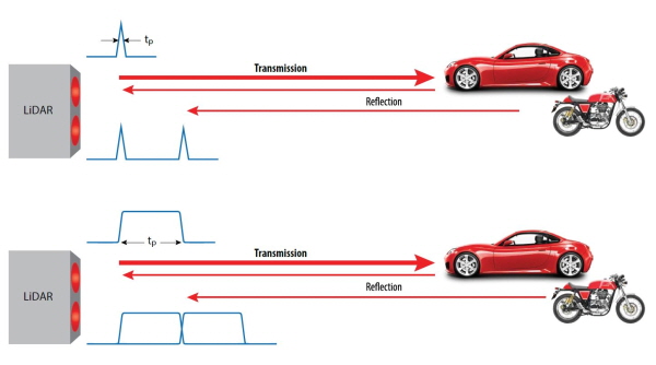
그림 3 ┃분해능에 대한 라이다 펄스폭의 영향.
위: 좁은 펄스는 반사를 쉽게 구분할 수 있도록 해준다.
아래: 넓은 펄스는 겹칠 수 있으며, 이로 인해 구분이 어려워지고,
거리 분해능을 감소시킨다.

레이저 드라이버
라이다를 위한 일반적인 펄스 레이저 드라이버는 레이저와 직렬로 연결된 반도체 스위치와 전기 에너지 소스를 사용한다. 성능은 부유 인덕턴스(Stray Inductance) 및 반도체 전력 스위치의 속도에 의해 제한된다.
지난 10년 동안에는 동급 실리콘 MOSFET에 비해 매우 낮은 인덕턴스와 최대 10배 더 뛰어난 스위칭 성능 지수(FOM: Switching Figures of Merit)를 제공하는 GaN(Gallium Nitride) 전력 FET가 상용화되었다.
.jpg)
그림 4 ┃EPC2016C 100V, 75A, 16mΩ eGaN FET의
크기는 2.1mm x 1.6mm이다.
EPC2212는 동일한 풋프린트와 유사한 등급을 갖춘 자동차 인증 부품이다.
그림 4 는 75A 펄스를 제공하는 100V eGaN FET인 EPC2016C FET를 보여주고 있다. 기존 실리콘 MOSFET 기술에 비해 성능이 크게 향상된 eGaN FET는 주어진 피크 전류 성능에 대해 훨씬 빠른 스위칭으로 전환이 가능하며, 아직은 동시에 이를 충족시킬 수는 없지만, 레이저 부하에서 >100A의 전류와 <2ns의 펄스 폭 을 구현할 수 있다.
많은 종류의 레이저 드라이버 토폴로지가 있지만, 고전력에 적합한 두 가지 주요 토폴로지는 첨단 제어 공진형 레이저 드라이버와 전류 제한 듀얼 에지 제어 드라이버가 있다. 고속 애플리케이션의 경우 공진형 레이저 드라이버가 가장 일반적으로 사용되기 때문에 이러한 유형의 드라이버에 대해 주로 논의하도록 하겠다.
EPC9126 및 EPC9126HC 레이저 다이오드
드라이버 EPC9126 레이저 드라이버는 eGaN FET 및 레이저 다이오드의 성능을 테스트할 수 있는 다기능 플랫폼이다. EPC9126 및 EPC9126HC의 PCB는 동일하다.
두 드라이버는 몇 가지 다른 컴포넌트를 가지고 있기 때문에 상용 EPC9126이 더 낮은 피크 전류와 더 짧은 펄스를 갖는 반면, EPC9126HC는 이보다 높은 출력 전류와 더 긴 지속시간의 펄스를 갖게 된다.
주요 차이점은 표 1에 요약되어 있다. 이러한 차이점을 제외하고 보드는 동일하며, 별도로 지정하지 않는 한 이 애플리케이션의 모든 내용이 두 보드에 모두 적용된다.
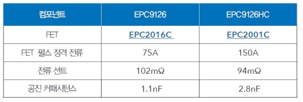
표 1 ┃EPC9126과 EPC9126HC의 차이점
따라서 두 드라이버를 통틀어 EPC9126xx로 총칭하도록 하겠다. 출하 시 두 드라이버는 모두 공진형 레이저 드라이버로 구성되어 있다. 이 드라이버의 기본 동작과 해당 설계 방정식은 다음 섹션에서 논의하도록 하겠다.
공진형 정전용량식 방전 레이저 드라이버 설계
그림 5 는 공진형 정전용량식 방전 레이저 드라이버의 간략한 회로도를 나타낸 것이며, 그림 6 은 주요 파형을 보여주고 있다.
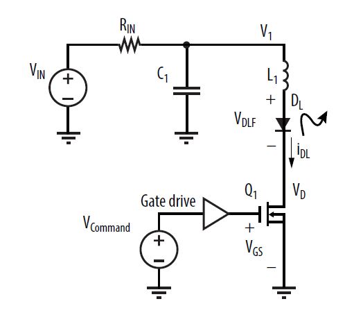
그림 5 ┃정전용량식 방전 공진형 드라이버
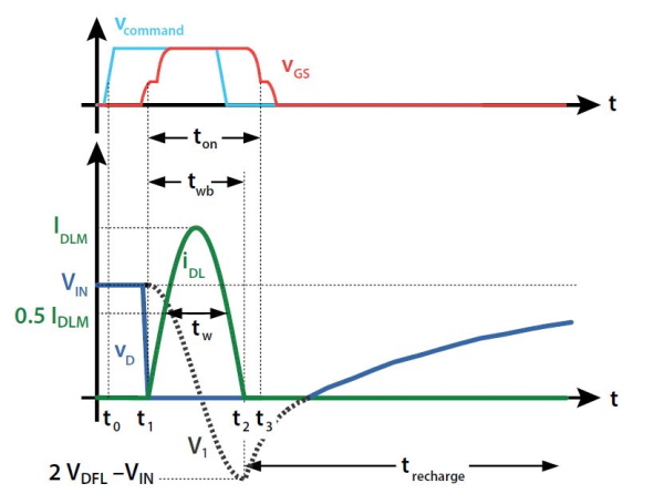
그림 6 ┃그림 5의 정전용량식 방전 공진형 드라이버의 주요 파형
Q1을 이상적인 스위치, 그리고 DL을 고정 순방향 전압 강하 VDLF를 갖는 이상적인 다이오드라고 가정하면, 이 드라이버는 다음과 같이 동작한다: Q1은 오프 상태에서 시작하므로, iDL = 0이다. 커패시터 전압 v1 = VIN이고, R1을 통해 충전된다. t = t 0에서 Vcommand는 게이트 드라이브를 트리거하고, t = t1에서 Q1을 완전히 턴온하며, 레이저 DL과 인덕터 L1을 통해 C1을 방전한다. C1과 L1은 공진 네트워크를 형성하기 때문에 iDL 및 vC1은 정현파 링을 이룬다.
유효한 초기 커패시터 전압은 레이저 다이오드의 순방향 강하로 인해 VC1,0 = VIN– VDLF이다. t = t2에서 iDL은 제로로 돌아가고, vC1 = 2 VDLF – VIN 이 된다. 이 지점에서 DL은 전류가 역전되는 것을 방지하고, C1은 R1을 통해 재충전된다. 스위치 Q1은 t = t3에서 V1이 제로로 교차되기 전에 턴오프된다.
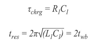
커패시터 충전 시간 상수 Tchrg와 공진 주기 tres는 다음과 같다:
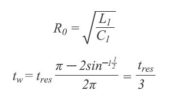
• 이 토폴로지는 부유 인덕턴스를 활용한다.
• 안정적인 펄스 형태
• 펄스 에너지는 VIN값을 통해 설정된다.
• 스위치는 간단한 드라이브를 위해 그라운드-레퍼런스된다.
• 게이트 턴-온 시에만 정밀 제어가 필요하다. (단일 에지 제어)
• 레이저 전류 펄스폭은 게이트 드라이브의 최소 펄스폭보다 짧을 수 있다.
부유 인덕턴스의 영향
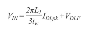
다음 방정식을 사용하여 피크 레이저 다이오드 전류 IDLpk를 계산할 수 있다:
.jpg)
드라이버 스위치 속성
위의 분석은 이상적인 스위치를 가정하고 있지만, 실제 반도체 스위치는 스위칭 시간이 제로가 아니며, 포화 전류 한계를 가지고 있다. 또한 스위치와 해당 패키지는 상당한 인덕턴스를 가질 수 있기 때문에 해당 펄스 형태에 필요한 전압을 증가시킬 뿐만 아니라 스위치 턴온이 느려질 수 있다.
과거에는 스위치 기술로 실리콘 전력 MOSFET이 선택되었다. 하지만 라이다 시스템의 보다 높은 성능을 구현하는데 있어 실리콘 전력 MOSFET은 두 가지 이유로 인해 주요 제한 요소가 되고 있다.
첫 번째는 전류 및 전압 요구사항을 충족시키기 위해 큰 다이 사이즈를 필요로 하기 때문에 게이트 전하가 커진다. 이로 인해 MOSFET의 턴온을 크게 지연시키게 된다.
두 번째로, 대형 MOSFET은 다이의 양면에 연결되는 수직 디바이스이라는 점이다. 이는 외부 패키지를 사용하도록 만들기 때문에 전력 루프와 게이트 드라이브 루프 모두 상당한 인덕턴스가 추가된다. 전자는 더 높은 전압을 필요로 하게 되고, 다이 크기도 커지게 되며, 후자는 디바이스의 턴온을 지연시킨다.
지난 수년 동안 GaN 기반의 새로운 전력 FET가 상용화되었다. GaN FET는 라이다 애플리케이션에서 실리콘 MOSFET에 비해 여러 압도적인 장점을 가지고 있다. 첫째, 동급 정격 전류의 MOSFET에 비해 최대 10배의 낮은 입력 커패시턴스 CISS를 가지고 있으며, 훨씬 더 빨리 GaN FET를 턴온할 수 있다.
둘째, GaN FET는 WLCSP(Wafer Level Chip Scale Package)를 사용할 수 있는 측면 디바이스이다. WLCSP는 매우 낮은 인덕턴스와 뛰어난 열 성능 및 높은 안정성, 추가 비용 최소화 등의 이점을 제공한다.
마지막으로, GaN FET의 다이는 동급의 전압 및 전류 등급을 갖춘 실리콘 전력 MOSFET 보다 훨씬 작기 때문에 인덕턴스를 줄이고, 멀티채널 라이다와 같은 애플리케이션을 위해 인접 레이저 간격을 좁힐 수 있다.
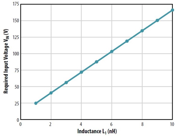
그림 7 ┃IDLpk = 30A, tw = 4ns, VDLF = 9V에 대한
버스 전압 Vin 대 인덕턴스 L
다음회에서는 이러한 이론을 기반으로 구현 가능한 기본 디자인 프로세스와 전반적인 실험 결과를 eGaN FET 기반으로 논의해 보도록 하겠다.
#본 기사에 관하여 E4ds.com에서는 라이다를 위한 GAN 기술에 대하여, 실험적 논의를 수행중에 있으니 본 기고 기술에 관한 질문이나 추가 기고를 원하는 경우 아래에 댓글을 달아주시기 바랍니다.

Comments
Related news
GaN technology improves efficiency and reduces size of power management systems
Imagine charging an electric vehicle twice as fast as today, or a motor drive achieving higher efficiency in half the current space, or carrying a laptop computer adapter in your pocket. The future of electronic devices depends on how we innovate power management technology.
2018.06.14by 명세환 기자
Infineon Presents Gallium Nitride Solution Product Family
Infineon Technologies is launching gallium nitride solution CoolGaN 600V e-mode HEMT and GaN EiceDRIVER IC products. With the launch of these products, Infineon now provides all power technologies spanning silicon (Si), silicon carbide (SiC), and gallium nitride (GaN). The CoolGaN 600V e-mode HEMT has begun supply, and the silicon-based GaN EiceDRIVER IC is available for pre-order.
2018.11.20by 이수민 기자
Keysight Announces WBG Semiconductor Power Device Analyzer
As the electric vehicle market grows, demand for ultra-compact, high-power, and high-efficiency electrical power systems is increasing. Consequently, the industry is seeking to adopt WBG semiconductor technology. However, many power converter designers are hesitant to adopt new technologies due to potential reliability and repeatability risks associated with characterization of next-generation semiconductors such as IGBTs and GaN. Keysight Technologies has announced the PD1500A dynamic power device analyzer, which includes a double pulse tester. The PD1500A provides repeatable WBG semiconductor measurement capabilities while ensuring the safety of the measurement hardware and the engineers performing the tests.
2019.07.31by 이수민 기자

Intel Unveils Next-Generation 'Core Ultra Series 3' and vPro Platform for Enterprise PCs
Intel has officially unveiled the "Intel Core Ultra Series 3" for next-generation enterprise PCs and the latest vPro platform, addressing a wide range of demands from enterprise notebooks to high-performance workstations.
2026.03.26by 배종인 기자

ROHM Launches ESD Protection Diode Compatible with High-Speed Interfaces of 10Gbps or Higher
Semiconductor specialist ROHM has developed the 'RESDxVx series' of ESD (electrostatic discharge) protection diodes capable of responding to next-generation high-speed data communication environments exceeding 10Gbps, simultaneously enhancing both signal quality maintenance required in high-speed interfaces and IC protection performance.
2026.03.26by 배종인 기자











