


Things to Know Before Buying a Switch Mode Power Supply
 Published2020.06.23 15:15
Monte Carlo analysis required to consider dynamic variables
Switching mode power supplies (SMPS) switch at a frequency that is fixed, variable, or synchronized to an external clock.
The physical size of the device varies depending on the switching frequency value, and the cost of the capacitors and inductors in the power supply also varies accordingly. Recently, there is a trend toward higher switching frequencies for more compact and economical circuit designs.
The oscillators built into switching regulator ICs are usually specified in the data sheet for a very wide frequency range. For example, the monolithic ADP2386 buck converter IC is guaranteed to operate within ±10% of the set switching frequency. Other common switching regulator ICs are specified at ±20% or even wider ranges.
The ADP2386, set to a switching frequency of 600 kHz by RT, can switch at 540 kHz, and even at an extreme of 660 kHz, considering that the switching frequency component variation of the ADP2386 is ±10%.
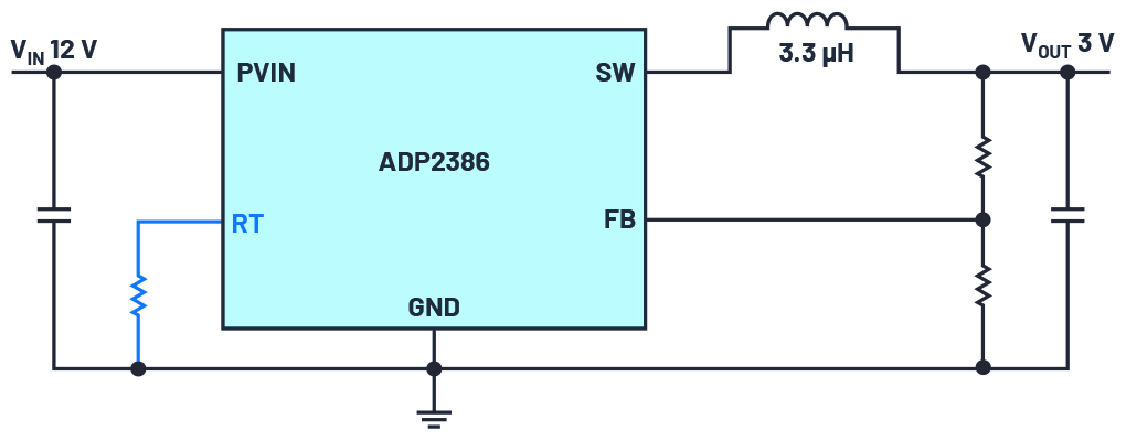
ADP2386 Buck Converter [Image = ADI]
Since the peak current of the inductor varies with the actual switching frequency, this total 20% possible switching frequency variation must be taken into account when designing the circuit. The inductor current ripple directly affects the output voltage ripple.
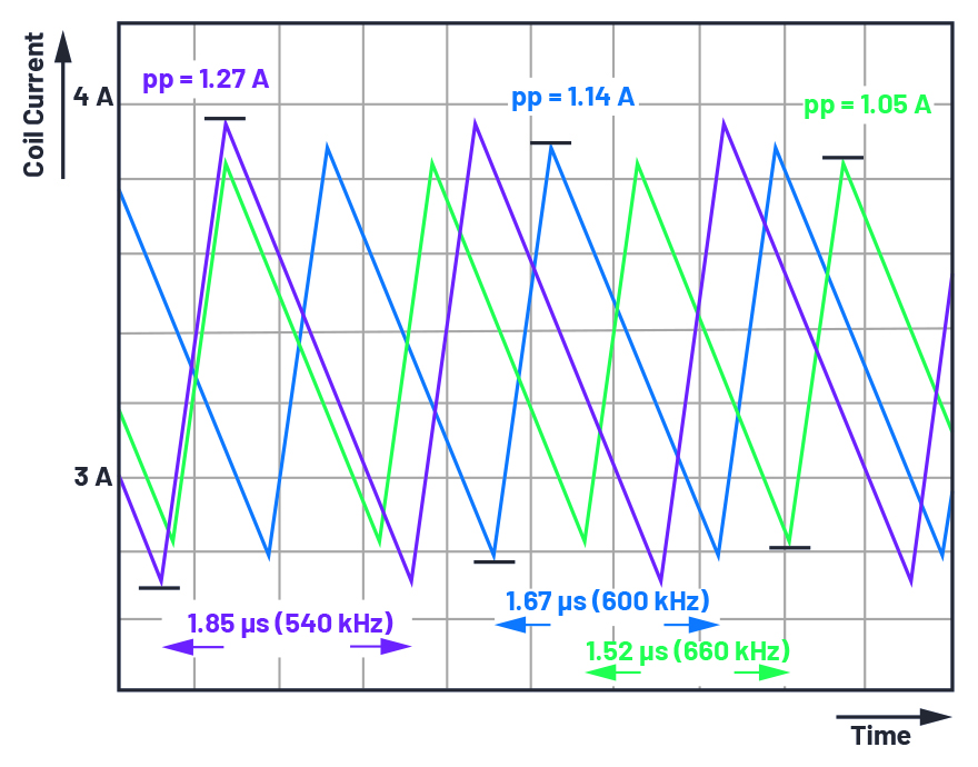
Coil current ripple peak-to-peak [Figure = ADI]
The figure above shows the effect of switching frequency on inductor current ripple. The nominal switching frequency of 600 kHz is shown in blue, the minimum (540 kHz) switching frequency is shown in purple, and the maximum (660 kHz) frequency is shown in green. At 600kHz nominal setting, we see a peak-to-peak current ripple of 1.27A when the regulator switches at 540kHz.
However, at the same frequency setting of 600 kHz, the switching regulator can also switch at 660 kHz, with a current ripple of 1.05 A. In this example, the difference in switching frequency between components in the circuit can result in a coil current ripple difference of 220 mA over the entire allowable temperature range.
The current limit setting of the switching regulator must be adjusted to account for these effects. The peak current must be sufficiently low to ensure that the existing overcurrent protection is not activated during normal operation. It should be noted that various possible deviations, such as the variation of the inductor and capacitor values, are not considered in this example.
For the output voltage ripple, the corresponding change in the current ripple can be seen in the values in Figure 3. This circuit is designed to generate a voltage ripple of 4.41 mV at a switching frequency of 600 kHz. For a switching frequency of 540 kHz, the voltage ripple is 5.45 mV, and at 660 kHz, a voltage ripple of 3.66 mV can be seen.
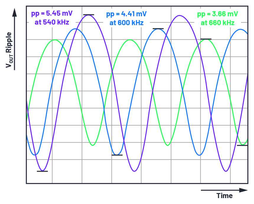
Changes in output voltage ripple due to deviation [Figure = ADI]
The only component variation considered in this example is the switching frequency variation over the allowable temperature range. In reality, there are many variables, such as variation in the actual values of inductors and capacitors, which are affected by the operating temperature. However, it can also be assumed that in most cases the actual variation of switching frequency will not reach the limit value of ±10%. Typically, this characteristic is centered around the typical value in the middle of the specified range.
Monte Carlo Analysis is used to systematically consider all dynamic variables of the power supply. Here, the deviations of other components and variable parameters are weighted and linked together according to their probability of occurrence. This Monte Carlo Analysis can be performed using simulation software such as 'LTspice®' from Analog Devices.
For information on varying parameters in an LTspice simulation, see LTspice: Worst-Case Circuit Analysis with Minimal Simulations Runs by Gabino Alonso and Joseph Spencer.
This article is a summary of an article titled “What to Consider in Regard to Switching Frequency” by Frederik Dostal, a field applications engineer at ADI.
Comments
Related news
.jpg)
Toshiba Launches Two 80V MOSFETs with Improved Power Efficiency
Toshiba has launched two types of 80V N-channel power MOSFETs suitable for power supply switching in industrial equipment such as data centers and telecommunications base stations. The TPH2R408QM features advanced SOP packaging, while the TPN19008QM employs advanced TSON packaging. Manufactured with the latest process technology, both devices reduce drain-source on-resistance by approximately 40% compared to the U MOSVIII H.
2020.03.30by 최인영 기자
.png)
Infineon Launches 'CoolSiC 1700V SMD MOSFET' to Improve High-Voltage Auxiliary Power Supply Efficiency
Infineon Technologies has launched the CoolSiC MOSFET 1700V product. The 1700V surface mount device (SMD) maximizes the physical properties of silicon carbide (SiC) and offers high reliability with low switching loss and conduction loss. It is suitable for auxiliary power supplies in three-phase conversion systems such as motor drives, renewable energy, charging infrastructure, and HVDC systems.
2020.06.17by 강정규 기자
ROHM Develops 1200V 4th-Generation SiC MOSFET with Reduced ON Resistance While Maintaining Short-Circuit Withstand Time
Rohm has developed a 1200V SiC MOSFET that reduces ON resistance without decreasing short-circuit withstand time. The newly developed fourth-generation product enhances the double trench structure, reducing the ON resistance per unit area by approximately 40% compared to the third-generation product. Additionally, by significantly reducing parasitic capacitance, switching loss has been reduced by approximately 50% compared to the third-generation product.
2020.06.17by 이수민 기자

Intel Unveils Next-Generation 'Core Ultra Series 3' and vPro Platform for Enterprise PCs
Intel has officially unveiled the "Intel Core Ultra Series 3" for next-generation enterprise PCs and the latest vPro platform, addressing a wide range of demands from enterprise notebooks to high-performance workstations.
2026.03.26by 배종인 기자

ROHM Launches ESD Protection Diode Compatible with High-Speed Interfaces of 10Gbps or Higher
Semiconductor specialist ROHM has developed the 'RESDxVx series' of ESD (electrostatic discharge) protection diodes capable of responding to next-generation high-speed data communication environments exceeding 10Gbps, simultaneously enhancing both signal quality maintenance required in high-speed interfaces and IC protection performance.
2026.03.26by 배종인 기자











