


Minimizing Machine Downtime with MEMS Accelerometers
 Published2020.12.19 07:55
Vibration detection and analysis, suitable for MEMS accelerometers
ADXL1002, capable of detecting vibrations from DC to 11kHz
Today, monitoring the condition of machinery and technical systems utilizing devices such as gears, motors, and generators is a critical task. Preventive maintenance is becoming increasingly important to minimize the risk of downtime, not only in the industrial sector but in all fields that use machinery. This is achieved through the detection and analysis of vibration patterns in machinery.
For example, vibrations generated by a gearbox are typically detected at multiple shaft speeds in the frequency domain. If inconsistent patterns are detected at different frequencies, this may be a signal indicating wear, imbalance, or loose component connections.
Micro-Electro Mechanical Systems (MEMS)-based accelerometers are often used for frequency measurement. Compared to piezoelectric sensors, MEMS sensors have high resolution and excellent drift and sensitivity characteristics. In addition, not only is the Signal-to-Noise Ratio (SNR) excellent, but it can also detect low-frequency vibrations at levels close to direct current (DC).
By utilizing Analog Devices (ADI) ’s ‘ ADXL1002 ’ low-noise, high-frequency MEMS accelerometer, it is possible to design highly linear and low-noise broadband vibration measurement solutions. These solutions are suitable for any application requiring a high dynamic range of up to ±50g and a frequency response from DC to 11kHz, such as bearing analysis or engine monitoring.
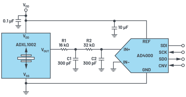
The figure above is an example of a circuit. The analog output signal of the ADXL1002 is passed through a 2-pole RC filter to the SAR (Successive Approximation Register) ADC ' AD4000 '. The AD4000 converts analog signals into digital values to enable additional signal processing tasks.
The ADXL1002 is a high-frequency single-axis MEMS accelerometer that provides an output signal passband extending beyond the sensor's resonant frequency range. Consequently, it can detect frequencies exceeding the 3dB bandwidth. The ADXL1002's output amplifier supports a signal bandwidth of 70kHz. It can directly drive capacitive loads up to 100pF. For loads greater than 100pF, a series resistor of 8kΩ or greater must be used.
An external filter at the output of the ADXL1002 is required to remove aliasing noise from the ADXL1002's output amplifier or other internal noise components. For example, such noise can occur due to the coupling of the internal 200kHz clock signal. Therefore, the filter bandwidth must be implemented accordingly.
With the conditions in the figure above (R1=16kΩ, C1=300pF, R2=32kΩ, C2=300pF), attenuation of approximately 84dB can be achieved at 200kHz. Additionally, the ADC sampling rate must be selected to be higher than the amplifier bandwidth, for example, 32kHz.
The designer must select the power supply voltage of the ADXL1002 for the ADC to be suitable for the corresponding reference, because the output amplifier is proportional to the power supply voltage. In this case, the power supply voltage tolerance and the voltage temperature coefficient (often connected to an external regulator) between the accelerometer and the ADC interact to offset the implicit errors associated with the power supply and reference voltages.
Frequency Response and Mechanical Considerations for Mounting of the ADXL1002
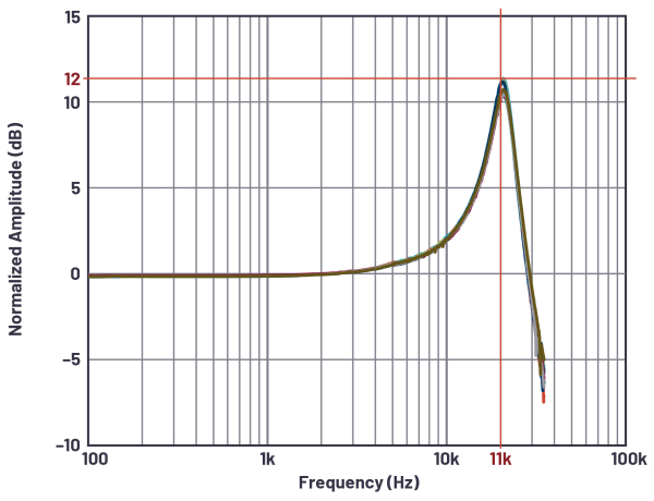
The frequency response of the accelerometer is the most important characteristic of the system, and the gain begins to increase from a frequency of about 2 to 3 kHz. At the resonant frequency (11kHz), the gain reaches a peak value of about 12dB (about 4 times) at the output voltage.
The ADXL1002 has an output (OR pin) to indicate measurement range overshoot (overrange). If severe overrange occurs, the built-in monitoring function generates a warning.
There are a few things to keep in mind when properly mounting the ADXL1002. To prevent measurement errors caused by vibrations of the circuit board itself, the sensor must be mounted on a solid point on the board. This causes the circuit board vibrations to exceed the mechanical sensor's resonance frequency, so they are effectively not detected by the accelerometer.
Fixing the sensor at multiple points and using a thicker board can also reduce the impact of system resonance on sensor performance.
This article is a summary of the article titled 'How to Build a MEMS-Based Solution for Vibration Detection in Condition Monitoring' written by Thomas Brand, a Field Application Engineer (FAE) at Analog Devices (ADI).
Comments
Related news

To improve the energy efficiency of industrial equipment, CbM technology must be introduced.
Seawater desalination technology requires substantial energy consumption. It also demands considerable time, money, and resources. ADI's Autosense platform provides an opportunity to achieve improved efficiency in this technology. Autosense is a CbM technology capable of continuously and accurately measuring and monitoring the integrity of equipment, and it can accumulate data regarding equipment condition faster and more accurately than other sensing platforms.
2020.10.26by 이수민 기자
ADI Announces Smoke Detector Reference Design and Algorithm
ADI announced the CN0537 reference design and algorithm that enable rapid prototyping of low-power smoke detectors in space-constrained form factors and faster time-to-market with reduced costs. The design reduces design risk by incorporating a smoke/fire detection algorithm validated through testing based on the 8th edition of the UL-217 smoke alarm standard.
2020.11.10by 이수민 기자
Yunggiwon Applyes Wireless Load Monitoring Technology to Real-World Sites
The Korea Institute of Civil Engineering and Building Technology (KICT), Lotte Engineering & Construction, and BuildIt jointly developed wireless load monitoring technology for system supports and applied it to the construction site of the Gwangmyeong Medical Complex Cluster project in Gyeonggi Province. The wireless load monitoring technology for system supports is a technique that remotely monitors the load on system supports, which are temporary skeletal structures that serve as support during concrete placement to ensure safety, using Bluetooth-based wireless load measurement sensors.
2020.12.15by 이수민 기자

Intel Unveils Next-Generation 'Core Ultra Series 3' and vPro Platform for Enterprise PCs
Intel has officially unveiled the "Intel Core Ultra Series 3" for next-generation enterprise PCs and the latest vPro platform, addressing a wide range of demands from enterprise notebooks to high-performance workstations.
2026.03.26by 배종인 기자

ROHM Launches ESD Protection Diode Compatible with High-Speed Interfaces of 10Gbps or Higher
Semiconductor specialist ROHM has developed the 'RESDxVx series' of ESD (electrostatic discharge) protection diodes capable of responding to next-generation high-speed data communication environments exceeding 10Gbps, simultaneously enhancing both signal quality maintenance required in high-speed interfaces and IC protection performance.
2026.03.26by 배종인 기자











