


Simplifying High-Performance Power Supply Design with Synchronous Controllers
 Published2021.05.14 10:25
스위칭 주파수 범위가 100kHz~3MHz
강제 연속 전도 및 버스트 모드 지원
아나로그디바이스(ADI) ‘LTC7803’ 동기식 스텝다운 컨트롤러는 고성능 전원장치의 간편한 설계를 지원한다. 이 컨트롤러는 N-채널 MOSFET 스위칭이 가능한 낮은 임피던스의 게이트 드라이버를 통합해 전반적인 컨버터 비용은 낮췄고 효율은 높였다. 대기 전류는 5mA이며, 40V에 이르는 입출력 전압 범위로 동작한다.
100kHz~3MHz의 넓은 범위로 스위칭 주파수를 설정할 수도 있다. 검출 저항이나 DCR 검출을 사용해 추가 효율 향상도 가능하며, 100% 듀티 사이클을 제공한다. 스프레드 스펙트럼 동작도 가능하며, 스위칭 주파수를 ±15% 범위로 조정함으로써 수월하게 EMC를 달성하게 하고 EMI 필터 비용을 낮춰준다.
◇ 회로도와 기능
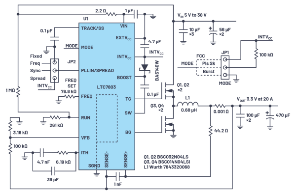
LTC7803 기반의 컨버터는 5V~38V 입력으로 3.3V, 20A를 제공한다. MOSFET Q1~Q4, 인덕터 L1, 입출력 필터 커패시터를 포함한다.
MODE 핀과 점퍼 JP1으로 강제 연속 전도(FCM), 펄스 스킵, ‘버스트 모드(Burst Mode®)’ 동작을 설정할 수 있다. 각 모드는 장단점이 있다. FCM은 전체 출력 전류 범위에 걸쳐서 출력 리플이 낮지만, 경부하에서 효율이 낮다. 버스트 모드 동작은 경부하 및 무부하 시 효율이 높지만, 경부하에서 출력 전압 리플이 높다.
LTC7803의 또 다른 장점은, 외부 클럭으로 동기화할 수 있으므로 호스트 시스템에서 서로 다른 주파수의 상호작용으로 인한 간섭 문제를 피할 수 있다는 것이다. 주파수 설정을 위한 점퍼 JP2를 사용하면 고정 주파수, 외부 클럭으로 동기화, 또는 스프레드 스펙트럼 동작을 선택할 수 있다.
MODE 핀을 GND로 연결하여 버스트 모드를 선택하고, 동기화를 활성화하면(PLLIN/스프레드 핀으로 클럭 펄스 제공) 컨트롤러가 FCM 모드로 동작한다. 다만, 경부하에서는 MODE 핀을 100kΩ 저항을 통해 INTVCC로 연결하는 펄스 스킵 모드가 FCM 대비 훨씬 더 우수한 효율을 제공한다.
◇ 효율과 스프레드 스펙트럼 동작
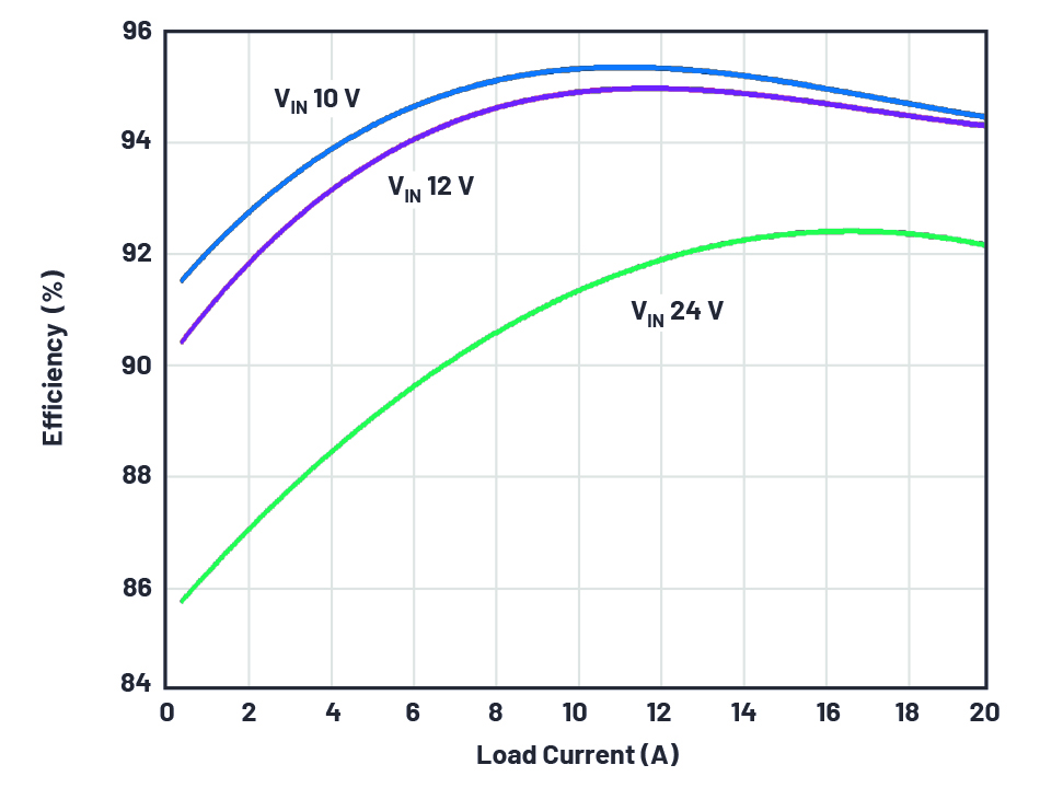
컨버터 효율 [그림=ADI]

위는 버스트 모드일 때 서로 다른 입력 전압에 대한 컨버터 효율을 보여준다.
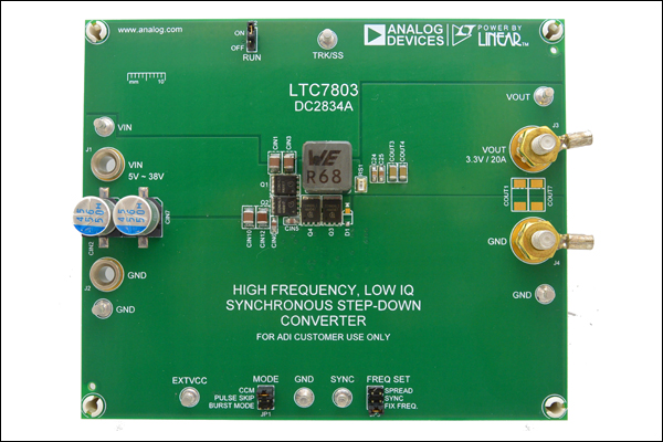
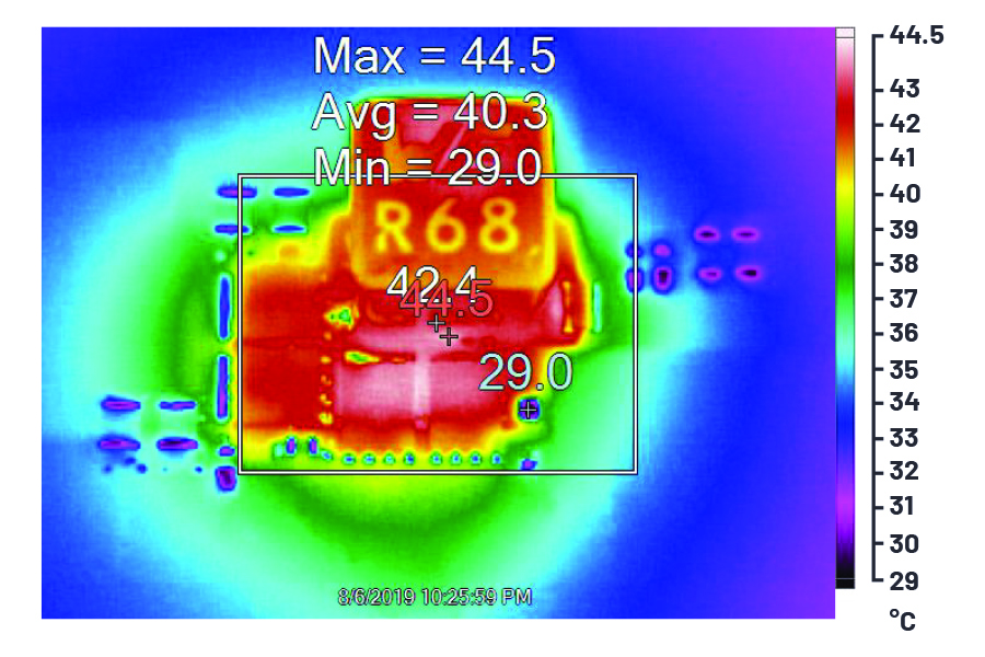
자연 대류 냉각을 사용했다 [사진=ADI]
위는 LTC7803 평가 작업에 사용된 DC2834A 데모 보드와 풀 부하일 때 DC2834A의 열화상 장면이다. LTC7803의 가장 큰 장점은 스프레드 스펙트럼 동작이 가능하다는 것이다. 이는 컨버터의 복사 잡음과 전도 잡음을 크게 낮추고, EMI 표준에 대한 전체 시스템 차원의 적합성을 손쉽게 달성할 수 있게 한다.
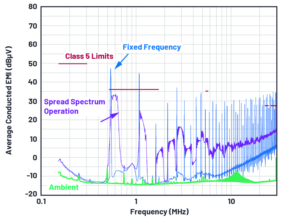
위는 CISPR 25 클래스 5 한계 요건에 대해서 스프레드 스펙트럼 동작을 사용할 때와 사용하지 않을 때의 2가지 전도 EMI 성능을 비교해서 나타낸 것이다.
LTC7803은 IQ가 낮은 동기식 스텝다운 컨트롤러 제품으로, 고도로 효율적인 전원 컨버터를 간편하게 설계할 수 있게 해준다. 넓은 입출력 전압 범위에서 동작하며, 최적의 과도 응답 특성을 달성한다. 버스트 모드와 스프레드 스펙트럼 동작 같은 기능들을 사용해서 효율을 높이고 EMI 적합성을 손쉽게 달성할 수 있다.
해당 기사는 아나로그디바이스(ADI)의 빅터 카시에프(Victor Khasiev) 선임 애플리케이션 엔지니어가 저술한 'LTC7803을 사용한 고성능 전원장치 설계 간소화 방법(LTC7803 or Easy Design Path to Advanced Power Supply)'라는 제목의 글을 정리한 것입니다.
Comments
Related news
.jpg)
Infineon Launches 1200V SiC IPMs, Reducing EMI Impact
Infineon has launched a 1200V transfer molding silicon carbide high-density power module. The CIPOS maxi IPM IM828 series is the industry's first 1200V IPM based on SiC, featuring excellent thermal conductivity and support for a wide range of switching speeds, making it suitable for three-phase AC motors and permanent magnet motors in variable speed drive applications such as industrial motor drives, pump drives, and active filters in HVAC systems.
2020.12.08by 이수민 기자
.jpg)
Optimizing Power Supply Efficiency Using a 6-Phase Buck Controller
Processors used in communications, server, and computing systems require core power supplies that deliver load currents exceeding 200A. These systems must meet stringent efficiency and performance requirements while maintaining a small PCB footprint. The ADI 6-phase dual-output buck controller, LTC7852 and LTC7852-1, which do not employ internal gate drivers, satisfy these requirements.
2021.03.17by 이수민 기자

TI Unveils Industrial and Automotive Power Solutions Featuring Active EMI Filters
As the proportion of electronic components increases in industrial and automotive applications, reducing electromagnetic interference (EMI) has become increasingly important. Texas Instruments' LM25149-Q1 and LM25149 synchronous DC/DC buck controllers integrate active EMI filtering (AEF) and dual random spread spectrum (DRSS) technology to reduce the board area occupied by external EMI filters and lower conducted EMI in power solutions across the entire frequency band of CISPR 25 Class 5.
2021.04.08by 이수민 기자

Intel Unveils Next-Generation 'Core Ultra Series 3' and vPro Platform for Enterprise PCs
Intel has officially unveiled the "Intel Core Ultra Series 3" for next-generation enterprise PCs and the latest vPro platform, addressing a wide range of demands from enterprise notebooks to high-performance workstations.
2026.03.26by 배종인 기자

ROHM Launches ESD Protection Diode Compatible with High-Speed Interfaces of 10Gbps or Higher
Semiconductor specialist ROHM has developed the 'RESDxVx series' of ESD (electrostatic discharge) protection diodes capable of responding to next-generation high-speed data communication environments exceeding 10Gbps, simultaneously enhancing both signal quality maintenance required in high-speed interfaces and IC protection performance.
2026.03.26by 배종인 기자











