


Selecting the right electronic components with the DAC error rate calculator
 Published2021.07.16 13:45
ADI DAC Error Rate Calculator, DAC Connection Components
Improve your signal chain by calculating each error distribution.
Electronic devices are composed of various electronic components such as sensors, actuators, amplifiers, analog-to-digital converters (ADCs), digital-to-analog converters (DACs), and microcontrollers (MCUs), and the signal chain configuration is also diverse. Therefore, the accuracy of the entire signal chain is very important.
To improve accuracy, the errors of individual links in the entire signal chain must be calculated and minimized. This analysis can be a daunting task, depending on the complexity of the signal chain.
Thomas Brand, a field applications engineer (FAE) at Analog Devices (ADI), presents a tool that can easily and accurately calculate DAC signal chain errors in his article, “How to Best Calculate the Digital-to-Analog Converter Signal Chain Error Budget.” Using this tool, you can calculate the error distribution of each component connected to the DAC.
The ADI Precision Error Budget Calculator helps developers select the best component for their application. Typically, a DAC is not used alone in a signal chain, but is connected to a voltage reference and an operational amplifier that acts as a reference buffer. The errors of additional parts must be calculated individually and added together.
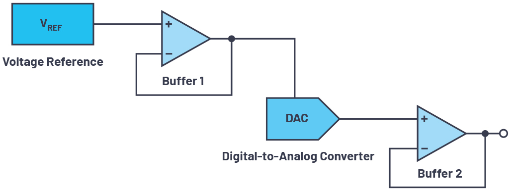
Brand FAE uses 'Figure 1' as an example to explain how each component affects the error. The voltage reference has four major error factors. The first is the initial error, which represents the change in the output voltage when measured at a temperature of 25℃ in the production test. In addition, there are temperature coefficient error, load regulation error, and line regulation error, for a total of four errors, with the initial accuracy and temperature coefficient error accounting for a large proportion.
In operational amplifiers, the biggest factors are the 'input offset voltage error', which is the low differential voltage that must be applied to the input to make the output 0 V, and the 'resistance tolerance', which is the gain error caused by the tolerance used to set the closed-loop gain. In addition, there are errors caused by bias current, PSRR (power supply rejection ratio), open-loop gain, input offset current, CMRR offset, and input offset voltage drift.
DACs have various errors listed on their data sheets. For example, integral nonlinearity (INL) error is related to the difference between the ideal output voltage and the actual measured output voltage for a particular input code. Other errors include gain, offset, and gain temperature coefficient errors. These errors are grouped together as the total unexpected error (TUE). It includes all DAC errors, including INL, offset, and gain errors, as well as output drift over power supply voltage and temperature.

Since each error source is usually uncorrelated, the most accurate way to calculate the total error in a signal chain is to use the above root sum square (RSS) formula. Calculating the error of each component is quite a tedious task. Using an error calculation tool, this calculation can be done easily, quickly, and accurately.
◇ How to use the precision DAC error rate calculator
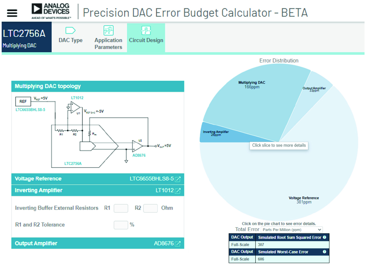
First, run the error rate calculator and choose between three DAC types. These are voltage output DAC, composite DAC, and 4mA-20mA current source DAC. Next, choose the desired temperature range and supply voltage ripple. Supply voltage ripple is important with respect to PSRR error. When you enter values, the calculation tool calculates the error distribution for each component in the signal chain and generates a chart like 'Figure 2'.
[Figure 2=ADI]
In the example, the voltage reference accounts for the largest proportion of the total error. This signal chain can be improved by using a more precise reference module.
In terms of DAC error, the resistors integrated into the DAC, which are used for comparing the internal inverting amplifier and improving accuracy, play a critical role. For DACs that do not include internal resistors or internal inverting amplifiers, these parameters can be expressed separately, as shown in Figure 2.
The ADI Error Rate Calculator is a reliable and easy-to-use calculation tool that allows you to easily create precision DAC signal chains and quickly evaluate your design.
Comments
Related news
.jpg)
ROHM Begins Supplying 32-bit DAC Chips for High-Quality Audio Devices
Rohm has commenced general sales of the 'BD34301EKV' 32-bit digital-to-analog converter IC for high-quality audio devices that reproduce high-resolution audio sources, as well as the 'BD34301EKV-EVK-001' evaluation board. The new DAC chip features a customizable built-in FIR filter, enabling manufacturers to perform their own sound quality tuning.
2021.02.06by 이수민 기자
ST Unveils High-Resolution Class-D Audio Amplifier for Automotive Applications
STMicroelectronics has launched the HFDA801A high-resolution audio amplifier for compact automotive applications. The HFDA801A is a PWM Class D amplifier capable of 2MHz switching and configured with a quad bridge topology. With an integrated high-performance DAC, it supports noise-free turn-on/off under all load conditions and ensures hi-fi audio quality without generating output artifacts.
2021.03.11by 명세환 기자
ADI Mass-Produces Digital Isolators Providing 10 Gbps Bandwidth
The ADN4624 digital isolator simplifies design and enables easy integration of isolation functionality for safety or data integrity. Meeting medical standards, it is a compact solution that reliably isolates Hi-Fi video and imaging links, precision analog front ends, and serial interconnects as an alternative to complex and specialized fiber optic solutions.
2021.07.01by 이수민 기자

Intel Unveils Next-Generation 'Core Ultra Series 3' and vPro Platform for Enterprise PCs
Intel has officially unveiled the "Intel Core Ultra Series 3" for next-generation enterprise PCs and the latest vPro platform, addressing a wide range of demands from enterprise notebooks to high-performance workstations.
2026.03.26by 배종인 기자

ROHM Launches ESD Protection Diode Compatible with High-Speed Interfaces of 10Gbps or Higher
Semiconductor specialist ROHM has developed the 'RESDxVx series' of ESD (electrostatic discharge) protection diodes capable of responding to next-generation high-speed data communication environments exceeding 10Gbps, simultaneously enhancing both signal quality maintenance required in high-speed interfaces and IC protection performance.
2026.03.26by 배종인 기자











