


[Technical Op-Ed] “Automotive Power Management ICs Must Maintain Low IQ and EMI”
 Published2021.10.08 11:32
Dispersive spectrum, broad frequency additive energy dispersion
While vehicle fuel efficiency is improving, the burden of electricity demand for various interior convenience features, telematics connectivity, and infotainment is increasing. Various information is conveyed to the driver via the vehicle's instrument panel or head-up display, and these functions are primarily operated via switches on the center console, which are commonly referred to as touchscreens or wireless head units.

▲Figure 1 Car instrument panel and center console
We will examine the challenges of providing multiple supply rails for these systems that use vehicle batteries as voltage inputs. Additionally, we will address the difficulties of meeting the required regulator output voltage range while maintaining low quiescent current (IQ) and EMI, and explore how new automotive power management ICs (PMICs) can address this issue as an alternative solution.
■ Automotive 'High-Efficiency' DC-DC Converter Essential
To limit heat generation in automotive applications, a high-efficiency DC-DC converter that meets manufacturers' stringent standby current requirements is required. This converter operates at low input battery voltages and supports emergency situations such as cold cranking and start-stop. A common method for managing cold crank is to use multiple PMICs (and other components) to lower the battery voltage with a two-stage buck regulator; however, this requires complex circuit design and layout, resulting in a large solution. This approach is vulnerable to EMI interference, making it difficult to meet EMI standards such as CISPR Class 5. Furthermore, in a load dump situation where the load is suddenly disconnected from the vehicle battery, a sudden spike in rail voltage can generate destructive levels of transient voltage, reaching as much as 40V.
■ Replaces the 2-stage voltage drop method of the integrated boost controller
A simpler way to replace the two-stage voltage drop method is to use the integrated PMIC MAX20057 as shown in Figure 2, and this product has many advantages over other automotive PMICs.
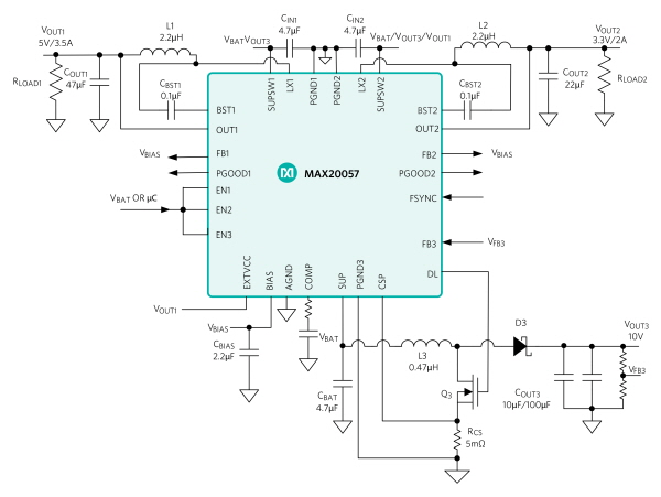
▲Figure 2. MAX20057 36V Boost Controller for Automotive Applications Equipped with 3.5A/2A Dual Synchronous Buck Converter
The high-density triple-output PMIC has two synchronous buck converters (3.5A, 2A) and supplies a regulated voltage (typically 10V) to the buck converters, and enables the regulated buck converters to remain regulated even when the battery voltage drops to a minimum battery input of 2V during operation in a cold crank state. The buck converter has a wide input voltage operating range of 3.5V to 36V and a very low operating current of 10μA (VOUT = 5V) and 8μA (VOUT = 3.3V), making it ideal for regulating voltage when a vehicle is not operating for a long time.
■ EMI mitigation, application of dispersed spectrum function
To address significant EMI-related concerns, the PMIC features a user-selectable dispersed spectrum function that significantly reduces peak EMI levels. This function reduces energy intensity while dispersing false energy across a wider frequency band.
The regulator switching frequency is fixed at 400 kHz or 2.1 MHz. The high switching frequency reduces the size of required external components and output voltage ripple, while preventing AM band interference. This PMIC is programmable and can operate in one of three modes for optimal performance: a forced fixed frequency operation mode, an ultra-low standby current skip mode, and a phase-locked synchronization mode for an external clock.
■ Increase in voltage conversion rate
Some automotive PMICs include buck regulators that supply low output voltages over a relatively wide input range, and these buck regulators are driven at low switching frequencies. This is because the minimum voltage conversion ratio (VOUT/VIN) is limited by the regulator's minimum adjustable on-time (typically 60ns to 120ns). For proper PWM (pulse width modulation) operation and optimal efficiency, the buck regulator must operate in continuous conduction mode (CCM) under normal operating conditions. In CCM, the minimum output-to-input voltage ratio is determined by the following formula.
For a typical buck regulator with a minimum on-time of 120ns and an input voltage of 12V, maintaining the CCM at 2.1MHz means that the output voltage cannot drop below 3V (realistically, to allow for design margin, the voltage minimum can be as low as 5V in some environments).
To obtain a low output voltage, pulse-skipping is required to reduce the effective duty cycle, but this can increase unwanted EMI. To maintain a consistent switching speed, the switching frequency must be lowered, but this also negatively impacts EMI performance.
This PMIC has an advantage over other automotive regulators in this regard. With a minimum typical on-time of only 20ns, this product's integrated buck regulator theoretically produces a minimum output voltage of 0.5V (for a 12V battery input with a switching frequency of 2.1MHz). This figure is lower than the specified minimum regulated output voltage (1V), meaning it can be used to supply low-voltage rails without lowering the switching frequency. Consequently, it ensures excellent EMI performance at low output voltage levels.
Other types of this PMIC include the MAX20457, a 3.5/2.5A dual buck converter without a boost controller, and the MAX20458, which features a 3.5A single buck converter and a boost controller. All versions are pin-compatible, enabling single-board designs for various applications. The operating temperature range for automotive applications is specified as -40°C to +125°C.
※ This technical contribution was written by Starry Tsai of Maxim Integrated (now part of Analog Devices).

Comments
Related news
Maxim Unveils Automotive LED Driver with Integrated Boost Converter
The number, size, and resolution of displays in automobiles continue to increase. However, maintaining consistent display brightness at all times places a burden on the power delivery system. In response, Maxim Integrated Korea has launched the MAX25512, a low-input-voltage 4-channel automotive LED backlight driver that integrates a boost converter.
2021.07.08by 명세환 기자

ADI Completes Acquisition of Maxim Integrated
Analog Devices (ADI) completed its merger with Maxim Integrated Products (MXIM), further strengthening its position as a high-performance analog semiconductor company with over $9 billion in annual revenue.
2021.08.27by 배종인 기자
ADI Announces Maxim MAXQ1065, IoT Security Encryption Controller
Currently, tens of billions of IoT devices are in use, and malicious hacking attacks are occurring against them. ADI has launched Maxim's 'MAXQ1065', an ultra-low-power cryptographic controller that strongly protects edge-to-cloud IoT nodes such as medical and wearable devices from security attacks by applying ChipDNA PUF technology.
2021.09.17by 이수민 기자

Intel Unveils Next-Generation 'Core Ultra Series 3' and vPro Platform for Enterprise PCs
Intel has officially unveiled the "Intel Core Ultra Series 3" for next-generation enterprise PCs and the latest vPro platform, addressing a wide range of demands from enterprise notebooks to high-performance workstations.
2026.03.26by 배종인 기자

ROHM Launches ESD Protection Diode Compatible with High-Speed Interfaces of 10Gbps or Higher
Semiconductor specialist ROHM has developed the 'RESDxVx series' of ESD (electrostatic discharge) protection diodes capable of responding to next-generation high-speed data communication environments exceeding 10Gbps, simultaneously enhancing both signal quality maintenance required in high-speed interfaces and IC protection performance.
2026.03.26by 배종인 기자











