This page was machine-translated and may differ from the original. View original
[Series] ST Engineer Yuji Kawano ⑤ - MCU, Arithmetic Operations via Logic Inversion and Shifting
MCU performs arithmetic operations using logic inversion and shifting
Subtraction cannot be performed directly; indirect calculation is performed using complements.
Multiplication with shifters and adders, division with shifters and subtractors
[Editor's Note] Generally, when people think of semiconductors, they tend to picture components familiar to the general public, such as computer CPUs and memory. On the other hand, the Micro Controller Unit (MCU), which serves as a core semiconductor for driving electronic products, is used in virtually every electronic device we encounter, yet remains an unfamiliar semiconductor to the general public. Recently, however, MCUs have begun to attract public attention as they have been frequently mentioned in the media due to the semiconductor shortage. Accordingly, this publication has organized a series of articles by Manager Yuji Kawano of STMicroelectronics, a company specializing in MCU semiconductors, to provide a professional look into MCUs.
First, let's look at addition, the simplest arithmetic operation.
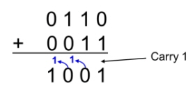
▲Figure 1. Binary addition
Binary addition is not significantly different from decimal addition. When the sum of the numbers in a specific column is 2, 1 is 'carried' to the left column. Figure 1 shows an example of adding two binary numbers [0, 1, 1, 0] and [0, 0, 1, 1].
For reference, adding 1 to the left column is called 'carrying', and subtracting 1 from the left column is called 'borrowing'.
Next, let's look at subtraction. As mentioned earlier, since the MCU cannot perform subtraction directly, it calculates it indirectly using the complement.
The complement x of a number y refers to the smallest value of x that results in a carry-over of x + y. In other words, when x and y are single-digit decimal numbers, the complement is the value of x such that x + y = 10. In the case of binary numbers, it refers to the value of x such that x + y = 2 (e.g., [1, 0]).
In decimal numbers, the 6's complement is 4, and the 3's complement is 7. In binary numbers, the 1's complement is [1], because [1] + [1] = [1, 0] (carrying one place from the first column to the second column).
As such, the complement of [1, 1, 0, 1] is [0, 0, 1, 1], because [1, 1, 0, 1] + [0, 0, 1, 1] = [1, 0, 0, 0, 0] (carry over to the left column by one whenever the sum of the two numbers becomes 2).
Then, how are complements used in subtraction? First, let's add an arbitrary number to the complement. For easier understanding, I will use decimal numbers.
Let's look at how to use complements to subtract the number 6 (subtrahend) from the number 9 (minuend). The complement of the subtrahend is 4, and adding this to the minuend gives the following:
9+4=13
If we subtract the carry-over from here, 3 remains, which is the result of subtracting 6 from 9.
9-6=3
This means that if you add the complement of the subtrahend and the minuend and then subtract the higher digit, you are effectively performing subtraction.
Next, I will use binary numbers. To subtract [1, 1, 0, 1] (13) from [1, 1, 1, 1] (15), the complement of [1, 1, 0, 1] is needed, which is [0, 0, 1, 1]. The result of adding the payoff to the minus is as follows.
[1,1,1,1] (15)+[0,0,1,1] (3) = [1,0,0,1,0] (18)
After that, if you remove the carry and look at the last 4 digits, it is [0, 0, 1, 0](2).
[1,1,1,1] (15) [0,0,1,1] (13)=[0,0,1,0] (2)
This means that, even in the case of binary numbers, adding the minuend to the complement of the subtrahend effectively performs subtraction.
In this way, subtraction can be performed using complements and addition, but the calculation to find the complement must be performed first.
▲Figure 2. Calculation of binary complement
The MCU can easily calculate the binary complement. This is possible by inverting each digit (i.e., [0] → [1] or [1] → [0]) and adding [1] at the end. An example is shown in Figure 2. To find the complement of [1, 1, 0, 1], invert each digit to [0, 0, 1, 0] and then add [1] at the end to get [0, 0, 1, 1]. The MCU can easily invert each digit of a binary number through an inverse logical operation. [1] The circuit for adding is called an incrementer, and it can be implemented simply by adding a circuit.
The complement can also be calculated using another method. This involves inverting all [1] and [0] from the highest digit up to the rightmost [1], while leaving the rest (including the rightmost [1]) as they are. For example, to find the complement of [1, 1, 0, 1], the highest digit ([1, 1, 0]) before the rightmost [1] is inverted, resulting in [0, 0, 1, 1]. In the case of the binary number [1, 0, 1, 0], the [1, 0] (the rightmost [1] and the next digit) is left as they are. The result is a complement of [0, 1, 1, 0]. However, because it is difficult for the MCU to determine the rightmost [1], the first complement calculation method is generally used, which involves inverting all digits (i.e., all bits) and adding [1].
Then, how should multiplication be performed? Based on basic principles, the simplest and easiest method of multiplication is to add the multiplicand (i.e., the number being multiplied) to the multiplier (the number being multiplied) the number of times equal to the multiplier (the number being multiplied). This method can be implemented using adders and counters. While this method is easy to use when multiplying simple 1- or 2-digit multipliers and multiplicands, multiplying 32-bit (i.e., 32-digit) numbers may require performing up to 2 to the power of 32 (4,294,967,296) additions. Although MCUs are fast, performing calculations on that scale is unrealistic.
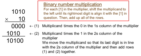
▲Figure 3. Examples of binary multiplication
Let us consider the case where binary numbers were multiplied using long multiplication. Figure 3 shows the calculation method [1, 0, 1, 0] x [1, 0] using such a method. Here, (1) is the result of multiplicand x multiplier 1 column, and (2) is the result of multiplicand x multiplier 2 column. In (1), since the number in multiplier 1 column is [0], the product becomes [0, 0, 0, 0]. In (2), since the number in multiplier 2 column is [1], the product is the result of shifting the multiplicand one position to the left (i.e., aligning it with the multiplier 2 column). Binary calculations are quite simple because they use only [1] and [0]. Basically, for every [1] of the multiplier, the multiplicand is shifted to the left so that the rightmost number aligns with the corresponding [1] of the multiplier, and then all columns are added.
Shifting positions in this manner is called 'shifting,' and the operation unit used to perform this is called a 'shifter.' Just like inverters, shifters can be easily manufactured. Therefore, multiplication can be performed using an MCU with only a shifter and an adder.
The simplest multiplication circuit (or minimum required circuit) consists of a 1-bit (single-digit) shifter and an adder. 32-bit (32-digit) binary multiplication is also possible by performing 32 shifts and a maximum of 32 additions. This means there is no need to perform up to 4,294,967,296 additions.
The simplest and easiest division method based on the basic principle is to keep subtracting the divisor (i.e., the number being divided) from the dividend (i.e., the number being divided) until the quotient is less than [1], and then count the number of subtractions. However, as with multiplication, it is unrealistic to have to perform up to 4,294,967,296 subtractions for a 32-bit dividend. Furthermore, while addition can be reduced in the multiplication process, subtraction cannot be reduced in the case of division, so division can be more difficult.
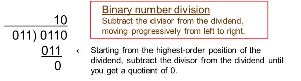
▲Figure 4. Example of binary division
I will perform the calculation using long division. Figure 4 shows dividing [0, 1, 1, 0] by [0, 1, 1] using long division. Since the divisor is a three-digit number, we can first divide the first three digits of the dividend (i.e., [0, 1, 1]) by the divisor (i.e., [0, 1, 1]). Unlike decimal numbers, binary numbers consist only of [1] and [0], so we simply subtract the divisor from the first three digits of the dividend. Then, we subtract the divisor from the next three digits of the difference and repeat this process until we reach the last digit of the dividend. As a result, we obtain the quotient and the remainder. In Figure 4, the dividend has four digits and the divisor has three digits. Therefore, two subtractions are sufficient. If the number of digits of the divisor and the dividend differs significantly, the number of shifts and subtractions increases, and consequently, the number of calculations also increases. However, if the number of digits of the divisor and dividend are the same, the calculation speed is increased because division can be performed with a single subtraction. Considering this, an MCU can perform division using this algorithm with only a shifter and a subtractor.
ARM's Cortex-M3 CPU has built-in subtractor hardware. The time required for division calculations ranges from 2 to 12 cycles (1 cycle = time to perform one calculation), and the number of cycles required for division depends on the number of digits of the divisor and dividend. If the number of digits of the divisor and dividend are the same, the calculation can be completed in 2 cycles, but if the number of digits is different, up to 12 cycles may be required.
I hope the above explanation has helped you understand the subtraction, multiplication, and division mechanisms of the MCU.
본 기사에 대한 정정·반론·추후보도 청구는 보도 청구 안내를, 그간 게재된 보도문은 정정·반론보도 모아보기를 참고해 주세요.