


[Serial] ST Maintenance Engineer Kawano ⑧ - Choosing an MCU Connection Tool: Determined by Purpose and Content
 Published2021.11.15 10:53
ICE provides enhanced debugging capabilities, including real-time tracing.
MCU vendors supply products with JTAG debugging modules.
[Editor's Note] When people think of semiconductors, they usually think of familiar semiconductors like computer CPUs and memory. Conversely, MCUs (Micro Controller Units), the core semiconductors that power electronic devices, are widely used in virtually every electronic device we encounter, yet they remain relatively unfamiliar to the general public. Recently, MCUs have been making headlines due to the semiconductor shortage, drawing public attention. Therefore, this magazine has prepared a series of articles by Yuji Kawano, Manager at STMicroelectronics, a company specializing in MCU semiconductors, to provide an in-depth look at MCUs.
 In the previous article on the development environment for MCU (microcontroller) software, we explained the overall development process, focusing on the tools and IDE (integrated development environment) required for system development using MCU. In this article, we'll cover the various tools available to connect your host PC to your target board (debug cables, in-circuit emulators, and other emulators) and how to choose the right one for your needs.
Debugging MCU software development requires tools to connect the host PC to the target board. Typically, two types of tools are available: in-circuit emulators and on-chip emulators. Let's examine the features of these tools.
■ Debugging by connecting the probe to an empty MCU socket on the target board with an in-circuit emulator
In-circuit emulators (ICEs) allow debugging by connecting probes to empty MCU sockets on the target board. ICEs internally emulate MCU functions and memory chips, allowing them to monitor and control signals on the target board in place of the MCU. The ICE's emulation function uses signals on the target board to emulate peripheral circuits, replacing the CPU. ICE's most notable feature is its enhanced debugging capabilities, such as real-time tracing. When problems arise during software development, ICEs can be used to identify the root cause. Nowadays, in-circuit emulators are often referred to as "full ICEs" rather than simply "ICEs" (Figure 1).
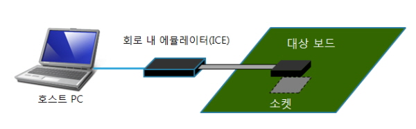
▲Figure 1: In-circuit emulator (ICE)
While ICE provides enhanced debugging features such as real-time tracing, it has the following drawbacks:
o The target board must have a socket.
o ICE hardware is expensive.
o You must select the appropriate ICE model according to the MCU specifications.
Because of these shortcomings, on-chip emulators are commonly used in MCU software development today. However, ICEs are still widely used for detailed software analysis. Naturally, some development engineers still seek to use ICEs from the earliest stages of software development.
■ Equipped with on-chip emulator, debug cable, and device command converter functions
Many MCUs today that have internally integrated flash memory also include an internal debugging module. When the IDE on the host PC issues a command such as "run the program" or "stop the program," the command converter installed in the debug cable (or target board) converts this command into something that the MCU's debugging module can interpret, and the debugging module transmits a command to the CPU according to the received command (Figure 2).
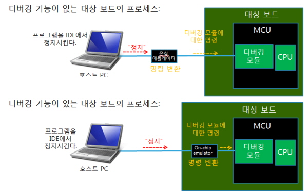
▲Figure 2: On-chip emulator
If the debug cable or device used to connect the host PC and the target MCU features a command converter function, it is called an on-chip emulator. On-chip emulators in use today can be broadly classified into the following two types.
o JTAG emulator
A JTAG emulator is a type of emulator developed by an organization called JTAG (Joint Text Action Group) with improved debugging capabilities based on board testing capabilities. Many MCU manufacturers provide MCU products that include JTAG debugging modules. In addition, many third-party companies (tool manufacturers) provide JTAG emulators for use with MCUs manufactured by their respective manufacturers. Therefore, for example, if two development projects require the use of different MCUs, both of which include JTAG debugging modules and have the same core type (or sometimes even different core types), the JTAG emulator can be reused, which means that the investment cost for tools can be reduced. STMicroelectronics (ST) offers the STM32 series of MCUs, all of which utilize the ARM® Cortex-M™ core (M0/M3/M4). ST also offers the ST-LINK/V2, a JTAG emulator compatible with this series.
o Dedicated emulator
This type of emulator is designed for use with MCUs that use a specific MCU vendor's proprietary core. Typically, MCUs with proprietary cores include their own proprietary debugging modules. Each MCU vendor or third-party vendor provides emulators to handle these proprietary debugging modules. Dedicated emulators are optimized for their respective debugging modules and cannot be used with modules from other vendors. Therefore, they are not universal.
More information about in-circuit and on-chip emulators can be found on the websites of these third-party vendors.
Depending on the MCU selected, the debugging module installed on that MCU will vary. If the MCU includes a JTAG module, a JTAG emulator will be required. Similarly, if the selected MCU uses a proprietary core, a debugging module compatible with that core will be required, and accordingly, a suitable dedicated emulator will be required.
Therefore, the type of on-chip emulator you choose depends on the MCU you're using. Furthermore, the choice between an on-chip emulator and an in-circuit emulator can be determined by the debugging purpose and the content you want to debug.

Comments
Related news
.jpg)
[Series] ST Engineer Yuji Kawano ⑤ - MCU, Arithmetic Operations via Logic Inversion and Shifting
A manager at STMicroelectronics, Yuki Kawano, explains methods for performing arithmetic operations such as addition, subtraction, multiplication, and division using an MCU.
2021.10.15by 명세환 기자
.jpg)
[Serial] ST Yuji Kawano Engineer ⑥ - Various Operational Tasks ALU, MCU 'Core'
MCUs are unfamiliar compared to CPUs or GPUs, yet they are among the most widely used semiconductors. Let's hear from Yuji Kawano, Manager at ST System Solutions Lab, about the versatility and potential of MCUs.
2021.10.25by 명세환 기자
.jpg)
[Serial] ST Yuji Kawano Engineer ⑦ - The Language of MCU, 'C'
MCUs are unfamiliar compared to CPUs or GPUs, yet they are among the most widely used semiconductors. Let's hear from Yuki Kawano, manager at ST's System Solutions Lab, about the applicability and potential of MCUs.
2021.11.09by 명세환 기자

Intel Unveils Next-Generation 'Core Ultra Series 3' and vPro Platform for Enterprise PCs
Intel has officially unveiled the "Intel Core Ultra Series 3" for next-generation enterprise PCs and the latest vPro platform, addressing a wide range of demands from enterprise notebooks to high-performance workstations.
2026.03.26by 배종인 기자

ROHM Launches ESD Protection Diode Compatible with High-Speed Interfaces of 10Gbps or Higher
Semiconductor specialist ROHM has developed the 'RESDxVx series' of ESD (electrostatic discharge) protection diodes capable of responding to next-generation high-speed data communication environments exceeding 10Gbps, simultaneously enhancing both signal quality maintenance required in high-speed interfaces and IC protection performance.
2026.03.26by 배종인 기자











