


[Technical Contribution] Tamer Kira & Nazareno Rossetti: ADI's Solution for Simplifying Electric Vehicle Junction Box Design
 Published2022.06.14 11:47
간소화된 시스템 아키텍처 저렴한 커패시터 활용 비용 절감
MAX17852, 셀 전압 노드·전류·온도·시스템 263μs만에 측정
■ 정션박스 충전시스템·인버터/모터·배터리팩 고전압 연결 제어
전기 자동차(EV)는 800V 이상의 동작 전압과 40A의 평균 전류를 달성할 수 있는 직렬 연결된 긴 배터리 스트링으로 구성된 대용량 배터리 뱅크(그림 1)에 의해 전원을 공급받는다.
각 셀 전압은 제어 모듈에 의해 모니터링 되며, 필요한 경우 적절한 제어 방법을 적용해 셀 간 전압 차이를 매우 작은 허용오차 내로 유지한다.
정션박스(junction box)는 충전 시스템, 인버터/모터 및 배터리 팩에 대한 고전압 연결을 제어한다.
고전압 연결, 전류 및 절연 저항은 이러한 모듈 내에서 측정되고 주 ECU로 다시 보내져 SOC 및 전력 계산과 차량 상태 모니터링에 사용되고 다양한 차량 조건에서 안전을 보장한다.
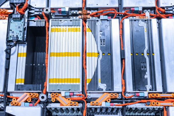
▲그림 1. 전기 자동차 배터리 팩과 배선
이 설계 솔루션에서는 관련된 정션박스와 함께 일반적인 EV 배터리 시스템의 구조를 살펴본다.
그런 다음 간소화되고 시스템에 매끄럽게 통합되어 시스템의 나머지 부분과 시간 정렬된 측정을 보고할 수 있는 새로운 정션박스 설계를 소개한다.
■ 분산형 배터리 시스템 아키텍처
그림 2는 일반적인 분산형 배터리 시스템을 보여준다. 일례로, 배터리 팩의 왼쪽에는 고전압 보드에 8개의 감시 모듈(N=8)이 있고, 각각은 직렬 연결된 14열(K=14)의 셀을 제어하며, 각 열은 병렬 연결된 70개의 배터리로 구성된다(7,840개의 Li+ 배터리 직병렬 조합).
절연은 마이크로프로세서와 첫 번째 모듈 사이, 그리고 모듈과 모듈 사이에 필요하다. 데이터는 이후 저전압 보드의 마이크로컨트롤러에 전달된다.
배터리 팩의 오른쪽에 있는 정션박스는 6개의 임계 전압 노드(접점 X 및 절연 ISO_RES)를 감지하고 홀 센서(Hall sensor)가 전류를 측정한다. 그런 다음 데이터가 2차 마이크로프로세서로 전달된다.
릴레이(contactor) 전압 노드를 모니터링 하는 것은 릴레이가 닫히고 열릴 때 배터리 상태를 확인하는 데 중요하다.
또한 이 모니터링은 릴레이가 정상 상태에 있을 때 시스템에 이를 알려주므로 안전에 필수적이다.
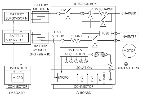
▲그림 2. 일반적인 시스템 아키텍처
■ 간소화된 시스템 아키텍처
그림 3의 간소화된 구현에서는 DC 블로킹 커패시터(또는 트랜스포머)가 서로 다른 공통 모드 전압으로 동작하는 데이지 체인 디바이스를 절연하는 데 사용된다.
모듈 간 데이지 체인에 저렴한 커패시터를 사용할 수 있으므로 시스템 비용이 절감된다.
뿐만 아니라 이 데이지 체인은 정션박스 데이터 수집 IC를 통합할 수 있도록 쉽게 확장이 가능해 로컬 마이크로프로세서를 사용할 필요가 없으며, 정션박스의 측정과 배터리 모듈의 측정 사이에 시간 정렬이 가능하다.
시간 정렬은 전력 관리와 계산에 보다 정확한 상관관계를 제공하기 때문에 중요하다.
마지막으로 정션박스 고전압 데이터 수집 IC는 션트 저항(그림에 표시됨)이나 홀 효과 전류 센서를 사용하거나, 또는 둘 다(이중 구성) 사용할 수 있는 유연성을 제공하는 전류 감지 기능을 갖는다.
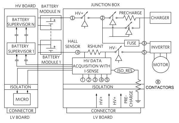
▲그림 3. 간소화된 시스템 아키텍처

■ 전류 감지 기능의 고전압 데이터 수집
일례로 MAX17852는 고전압 및 저전압 배터리 모듈 관리를 위한 유연한 데이터 수집 시스템이다.
이 시스템은 완전한 이중구성 측정 엔진을 가지고서 14개의 셀 전압 노드(또는 7개의 접지 기준 고전압 노드), 1개의 전류, 그리고 4개의 온도 또는 시스템 전압 조합을 263μs만에 측정할 수 있다.
또한 고속 ADC SAR 측정 엔진만으로 156μs 이내에 모든 입력을 폴링 할 수도 있다.
이 고도로 통합된 배터리 센서는 견고한 데이지 체인 방식의 직렬 통신을 위한 고속 차동 UART 버스를 통합하고 있으며, 잡음 내성을 극대화하도록 설계됐다. 최대 32개의 디바이스를 데이지 체인 방식으로 연결할 수 있고, 단일 데이지 체인으로 정션박스와 배터리 감시 측정 간에 시간 정렬이 가능하다. 이에 따라 셀 전압, 버스 바 측정, 팩 전압, 팩 전류, 릴레이 전압 및 온도 측정이 10?s 이내에 정렬된다.
이 시스템은 견고한 통신을 위해 아나로그디바이스의 배터리 관리 UART 또는 SPI 프로토콜을 사용하며, 외부 디바이스 제어를 위해 I2C 마스터 인터페이스를 지원한다.
시스템은 ASIL D 및 FMEA 요구사항을 지원하기 위해 임베디드 통신 및 하드웨어 경고 인터페이스 둘 다를 통해 내부 진단 및 신속한 경고 통신의 간소화된 기능 세트를 지원하도록 최적화되었다.
■ 배터리 전기 절연 측정
미국 교통부(DOT)는 이러한 측정에 대해 다음과 같이 규정하고 있다(TP-305-01). 저항(ohm)은 전기추진 배터리의 음극(양극) 측과 차량 섀시 사이에서 SAE 1766에 따라 차량의 공칭 동작 전압(볼트)의 약 500배가 되어야 한다. 즉, 400V의 경우 200kΩ이어야 한다.
이에 따라 섀시와 배터리 양극(음극) 사이의 절연 저항 RLEAK-(RLEAK+)은 그림 4에 보이는 네트워크로 감지할 수 있으며, 데이터 수집 IC의 AUX 핀에 전압으로 보고된다.
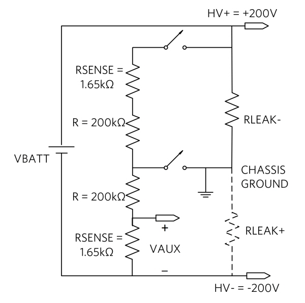
▲그림 4. 배터리 절연 저항 측정
그림 4의 네트워크에 따르면 RLEAK- 경우에 대한 VAUX 식은 다음과 같이 나타낼 수 있다.
이 식에서:
여기서:
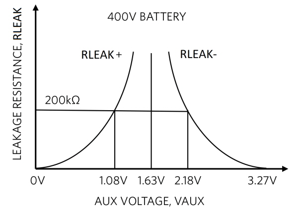
아래 그래프는 RLEAK+와 RLEAK-에 대한 곡선을 모두 표시한다. 여기서 200kΩ RLEAK- 절연 저항이 2.18V의 감지된 전압 VAUX를 생성하는 데 반해, 200kΩ RLEAK+ 절연 저항은 1.08V의 감지 전압을 생성하는 것을 보여준다.
▲그림 5. 절연 저항 곡선
■ 전기 연결 접점 저항, 전류, 고전압 및 저전압 보드 간의 절연 저항 모니터링
전기 자동차는 고전압과 고전류를 이용하므로 안전한 작동을 보장하기 위해서는 전기 연결 접점 저항, 전류, 고전압 및 저전압 보드 간의 절연 저항을 모니터링 해야 한다. 이 글에서는 일반적인 전기차 배터리와 정션박스 시스템의 구조를 살펴보고 복잡성을 알아보았다.
다음으로 비용 효율적인 저잡음 용량성 절연 데이지 체인 통신 아키텍처인, 정션박스 전용 마이크로프로세서가 필요 없는 새롭고 독창적인 데이터 수집 IC를 소개했다.
이 IC는 정션박스와 셀 전압 측정 간의 시간 정렬이 가능하다. 또한 전류 감지 기능이 통합돼 별도의 홀 효과 전류 센서가 필요 없다.
고속 SAR ADC 아키텍처는 최소 시간에 다양한 측정이 가능하도록 해준다.
※ 저자 소개
▷테이머 키라(Tamer Kira)는 아나로그디바이스의 자동차 사업부 사업관리 총괄 디렉터이다. 현재 전기차, 하이브리드 및 플러그인 하이브리드 전기차를 위한 배터리 및 전력 관리에 관심을 갖고 있다. 전기공학 학사 학위를 받았다.
▷나자레노 로세티(Nazzareno (Reno) Rossetti)는 아나로그디바이스의 아날로그 및 전력 관리 전문가이다. 책을 출간하고 해당 분야의 여러 특허를 보유하고 있다. 이탈리아 토리노 공과대학에서 전기공학 박사 학위를 받았다.

Comments
Related news
.jpg)
[Op-Ed] ADI Engineer Hakan Wuenlu – “ICs with Overvoltage Protection OTT Are the Best”
Analog Devices' Senior FAE Hakan Uenlue explains how to protect circuits from overvoltage in the analog front end using OTA amplifiers.
2021.12.16by 명세환 기자
[Technical contribution] Thomas Brand ADI FAE-“Ethernet PHY must have low loss and withstand external conditions well”
We arranged a session to hear from Thomas Brand, Senior FAE at Analog Devices, about considerations when selecting an Ethernet PHY.
2022.03.15by 명세환 기자

[Technical Contribution] Starry Chai, ADI Manager – Automotive PMIC with Low IQ, Minimum On-Time, and Low EMI
We have arranged a session to hear from Starry Chai, an ADI manager, about solutions to resolve conflicting design challenges related to in-vehicle power supply and ways to simplify power design.
2022.05.17by 명세환 기자

Intel Unveils Next-Generation 'Core Ultra Series 3' and vPro Platform for Enterprise PCs
Intel has officially unveiled the "Intel Core Ultra Series 3" for next-generation enterprise PCs and the latest vPro platform, addressing a wide range of demands from enterprise notebooks to high-performance workstations.
2026.03.26by 배종인 기자

ROHM Launches ESD Protection Diode Compatible with High-Speed Interfaces of 10Gbps or Higher
Semiconductor specialist ROHM has developed the 'RESDxVx series' of ESD (electrostatic discharge) protection diodes capable of responding to next-generation high-speed data communication environments exceeding 10Gbps, simultaneously enhancing both signal quality maintenance required in high-speed interfaces and IC protection performance.
2026.03.26by 배종인 기자











