



[Technical Contribution] ADI's Stuart Merkel: How to Multiplex a Single 1-Wire Host into Multiple Channels
 Published2023.08.14 10:38
Rail-to-rail analog signal processing and low RON
Channel selection control MCU, must have extra GPIO pins
A 1-Wire network with many 1-Wire® nodes may require dedicated 1-Wire channels. This article describes how to have multiple 1-Wire channels while using only one 1-Wire host in the network.
■ Overcoming the disadvantages of using a 1-wire network and MUX
1-Wire networks were originally designed for communication between a single 1-Wire host and multiple 1-Wire nodes on a single 1-Wire bus. Whenever possible, a linear topology with only a few stubs is ideal for 1-Wire networks. However, star topologies with long stubs are often unavoidable, and in these cases, determining the effective limit can be difficult. One way to overcome this difficulty is to use analog multiplexers (MUXs) to split the star topology into multiple channels. The benefits of using multiple channels include faster access times for individual 1-Wire nodes, increased network robustness, and the ability to mix overdrive-specific nodes with standard/overdrive nodes on different channels. These benefits can be achieved by using a single 1-Wire host.
■ 1-wire host analog MUX common signal connection
When building a 1-Wire network with multiple channels, a common approach is to connect the 1-Wire host to the common signal of an analog MUX. Then, using the digital channel select signals of this MUX, connect the 1-Wire common signal to the desired I/O of the 1-Wire node device, which contains the channels. This method allows for connecting more 1-Wire nodes to the network than the maximum allowed on a single 1-Wire bus. This is possible because stubs are eliminated and the number of 1-Wire nodes per channel driven by the 1-Wire host is reduced.
■ The MUX you want to use must be capable of processing rail-to-rail analog signals.
Figure 1 shows a 3.3V system using a DS2485 1-Wire host. The microcontroller controls the DS2485 and MUX channel selection. In a 1-Wire network, the MUX used must be capable of handling rail-to-rail analog signals. Otherwise, signal distortion may occur and the VPUP parameter requirements of the 1-Wire node may be violated. Additionally, the RON parameter of the MUX should be as low as possible to avoid changing the active pull-up impedance (RAPU) of the DS2485. If this is not taken into account, the 1-wire node may not receive the current it needs to operate when a strong pull-up occurs.
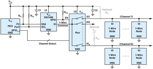
To power idle 1-wire nodes when the switch is open, external pull-up resistors (RP4 and RP5) can optionally be used after the MUX (U2). Otherwise, each time a channel switch is connected, the microcontroller must wait for the maximum startup time of the nodes connected to that channel (typically 2 ms) before communicating.
However, when using external pull-up resistors on each channel, the impact of the RON parameter of the MUX when pull-down occurs by the 1-wire host must be considered. This impact will be minimal if a low RON is chosen so as not to violate the highest 1-wire input low (VIL) parameter of the 1-wire nodes.
Therefore, for the corresponding MUX rear pull-up resistor RP and the corresponding MUX resistor RON, the MUX rear output low voltage can be expressed as follows.

Additionally, the flexibility of the 1-wire host you want to use is also an important consideration. Analog Devices recommends the DS2485 1-Wire host for 3.3V systems because it offers flexible timing, input triggering levels, and internal pull-up resistors. The DS2485 can also be configured in high-impedance mode, which is useful when using an optional external resistor. If your system requires 5V, the DS2484 is a viable alternative.
Some systems may require a mix of overdrive-only node devices and standard/overdrive 1-Wire node devices. Connecting overdrive-only devices and standard/overdrive devices to the same 1-Wire bus will result in communication failures. A simple solution is to use a MUX to connect the overdrive-only devices to a different channel than the standard/overdrive devices. The DS2485 can then switch between overdrive mode and standard mode, depending on the channel selected, and communicate appropriately.
■ Analog MUX selection
When selecting an analog MUX, design engineers must consider many factors. These include channel count, interface type, cost, package type, and performance. Table 1 lists recommended analog MUX products for 1-wire applications. All of the analog MUX products listed in this table can handle rail-to-rail analog signals, have low RON, and are available in a variety of package types. The microcontroller controlling channel selection must have spare GPIO pins. If your microcontroller doesn't have extra GPIO pins, you can use the MAX14661 or a similar device that can connect to the same I2C bus that the DS2485 uses.
.png)
▲Table 1: Analog MUX Selection Guide for 1-Wire
■ All device specifications are carefully reviewed under all conditions of use.
This article describes how to split a star topology 1-wire network into multiple channels using an analog MUX from the recommended list. As with any electronic component selection, the specifications of all devices intended for use in a system must be carefully reviewed under all operating conditions to ensure reliable operation.
■ List of related products
.png)
※ About the author
Stewart Merkel, AE / Analog Devices, Inc.
Stewart Merkel has been an applications engineer at ADI for over 10 years. Prior to that, he worked at Maxim Integrated, focusing on embedded security, 1-Wire devices, and secure and non-secure telecommunications equipment. He received his Bachelor of Science degree in Electrical Engineering from Binghamton University in New York State.

Comments
Related news

Intel Unveils Next-Generation 'Core Ultra Series 3' and vPro Platform for Enterprise PCs
Intel has officially unveiled the "Intel Core Ultra Series 3" for next-generation enterprise PCs and the latest vPro platform, addressing a wide range of demands from enterprise notebooks to high-performance workstations.
2026.03.26by 배종인 기자

ROHM Launches ESD Protection Diode Compatible with High-Speed Interfaces of 10Gbps or Higher
Semiconductor specialist ROHM has developed the 'RESDxVx series' of ESD (electrostatic discharge) protection diodes capable of responding to next-generation high-speed data communication environments exceeding 10Gbps, simultaneously enhancing both signal quality maintenance required in high-speed interfaces and IC protection performance.
2026.03.26by 배종인 기자
ST Launches 75V Drive IC Targeting 48V Industrial Motor Driving
ST Microelectronics has unveiled the 'STSPIN9P' series of 75V motor drive ICs tailored for 48V-class industrial drive system design. The new product family is characterized by half-bridge and full-bridge configurations that enable design scalability according to motor type and output conditions. Power supply circuits, protection functions, and current sensing circuits are integrated on-chip to simplify system configuration, and the devices are designed to support applications up to 500W maximum. The company plans to provide reference designs and demo boards to support development and evaluation in industrial automation, robotics, pumps, fans, lighting, and textile machinery.
2026.03.26by 배종인 기자

Nordic supports security updates for the entire lifecycle of IoT devices at a single fixed cost
Nordic Semiconductor, a global leader in low-power wireless connectivity solutions, has unveiled a single fixed-cost licensing model that delivers FOTA (Firmware Over-the-Air) and device management capabilities throughout the device lifecycle via nRF Cloud, and introduced a new firmware update solution to prepare for the enforcement of the European Union's Cyber Resilience Act (CRA).
2026.03.26by 배종인 기자

Practical Training in Low-Noise, Low-Power Circuit Design All in One Place… Training Fee Support
The "2026 Advanced Engineer Practical Masterclass" to strengthen competencies in high-sensitivity analog circuit and sensor-based system design will be held on April 16 at the e4ds Conference Center in Gasan-dong, Seoul. This program will be conducted as an offline paid hands-on training session, not online, and is targeted at engineers seeking on-site intensive learning. Texas Instruments will provide educational support for this training, allowing participation at 150,000 won, a 100,000 won discount from the original price of 250,000 won.
2026.03.26by 배종인 기자











