마이크로칩 8월
This page was machine-translated and may differ from the original. View original

Teledyne LeCroy Launches Motor Drive Analyzer

Google 우선 소스Published2015.02.05 16:11
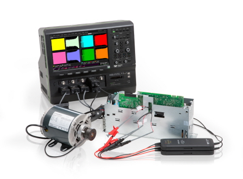
February 5, 2015 — Teledyne LeCroy Korea (General Manager Woon-Jae Lee, teledynelecroy.co.kr) announced today the MDA8000 series motor drive analyzer, which features three-phase power analyzer steady-state calculation, special dynamic three-phase power and mechanically operated motor analysis capabilities, and high bandwidth (1GHz) with built-in control system debugging all in one instrument.


Motor drive analyzers are based on the HDO8000 oscilloscope platform and come standard with 8 input channels (16 digital channels optional), 12-bit resolution, a sample rate of 2.5 GS/s, up to 1 GHz bandwidth, and up to 250 Mpts/ch accumulation memory. Serial trigger/decode and analysis software options, along with a wide range of voltage and current probes, are available for use with the motor drive analyzers.

The motor drive analyzer will be used by designers and manufacturers of motors, motor drives, variable speed drives, variable frequency drivers, industrial automation, motion control equipment, and motion control devices. Design engineers designing products that utilize motors—such as automobiles, power tools, home appliances, elevators, fans, blower compressors, and pumps—will use this product to evaluate their developed products, verify control status, and finalize the design of drive systems. Of course, even when designing a three-phase system without a motor, a motor drive analyzer can be used for basic three-phase power system analysis and debugging.

Complete drive system authentication and debugging capabilities
A complete drive system consists of three-phase power electronics, analog and digital sensors for motors/machines, and embedded controls containing complex and diverse analog, digital, and serial data and pulse width modulation signals. While a standard 8-bit oscilloscope can capture the operation of high-speed embedded control systems or power transistors, it has been impossible to measure drive power and efficiency until now. Although power analyzers are used as a single tool to measure input/output drive power and efficiency, they capture embedded control waveforms only to a limited extent or cannot capture them at all, and they do not provide drive system debugging capabilities.
+more+
The motor drive analyzer captures and measures waveforms of the drive power supply and individual power transistors, as well as analyzes waveforms of the embedded control system. It performs three-phase power analysis using power waveforms captured from high-performance equipment, enabling analysis and debugging from every perspective of the complete motor driver.
More information than “numbers”
Various voltage, current, power (active power, apparent power, reactive power), phase angle/power factor, and efficiency parameters are calculated from the captured voltage and current waveforms, and the resulting values are displayed in a table. The table is user-configurable and displays the information typically provided when measured in the power analyzer's "steady-state" operating mode.
Additionally, the motor drive analyzer provides numerical calculations under dynamic operating conditions. It generates a waveform showing the change in measured parameters for every cycle, and the generated waveform can be displayed simply by selecting a value from the table. This waveform is temporally correlated with other waveforms collected by the motor drive analyzer and is used to demonstrate the complex associations with other control or power system waveforms and debug drive system issues. Statistical details of the measurement set are also displayed. The displayed information provides more valuable insights than what the power analyzer offers.

Dynamic Motor Drive Analysis
The long capture memory of the motor drive analyzer, capable of up to 250 Mpts/Ch, provides exceptional capabilities for analyzing the dynamic response of motors and drives. For example, it can continuously capture signals for 25 seconds while maintaining a sampling rate of 10 MS/s. This provides information that allows for a complete understanding of dynamic drive behaviors, such as motor startups, loads, or rapidly changing load conditions, and enables easy identification of the correlation between drive response issues and problems in the control system or power section. Zoom settings can be adjusted with a single Zoom+Gate mode button when magnifying voltage, current, mechanical parts, or other probed signals. Additionally, the displayed waveform and measurement table for each cycle are automatically selected and set as the magnification area. Furthermore, if the magnification ratio is changed or the position of the magnification area is shifted from the originally captured waveform, the measurements for the magnified area are immediately updated and displayed. This is a fast and powerful method for understanding motor drive systems and gaining a deep understanding of the root causes of abnormal motor behavior.

Flexible setup ability
The intuitive, graphical, user-centric interface guides you to easily set up/connect. The setup function allows you to configure all combinations of inputs and outputs for single-phase or three-phase drives, provides a 3-phase 2-wattmeter method and a 3-phase 3-wattmeter calculation method, and also provides a function to convert line-to-line voltage to line-neutral voltage. By probing using the 8 input channels of the HDO8000 oscilloscope and using the 3-phase 2-wattmeter method, it is possible to measure the input/output of the drive system and the output efficiency of the motor.


본 기사에 대한 정정·반론·추후보도 청구는 보도 청구 안내를, 그간 게재된 보도문은 정정·반론보도 모아보기를 참고해 주세요.
명세환 기자
명세환 기자