



Launch of Harmonics Calculation Option for Motor Drive Analyzers
 Published2015.11.13 18:32
On November 13, 2015, Teledyne LeCroy announced the Harmonics Calculation option for the MDA800 series motor drive analyzer. This optional software package enriches the basic specifications of the motor drive analyzer software by adding new harmonic order tables that include advanced harmonic filtering for AC input and drive output numerical table measurements, Total Harmonic Distortion (THD) measurement parameters for voltage, current, and power, and spectral waveform displays.
The basic motor drive analyzer software provides only Full Spectrum (without harmonic filter) or Fundamental harmonic filters. The newly released options add Fundamental+N and Range filters. The Fundamental+N filter allows users to specify the (N) harmonic quantity. While very similar to the Range filter, it differs in that users can set a starting point other than the Fundamental one. These filters provide flexibility and the ability to identify measurements affecting specific frequency bands to motor drive engineers who need to analyze heat generated by harmonic distortion during motor rotation or analyze whether specific harmonics significantly affect the drive's operating characteristics.
This approach is superior to a simple low-pass filter where the filter cannot be selected. In particular, for variable frequency drive outputs that undergo significant changes depending on the operating state, this advanced harmonic filtering function can be more effective because it cannot be filtered by a simple low-pass filter.
The harmonic calculation option added THD measurement parameters to the numeric table display. Along with other numeric table parameters, users can simply touch the numeric table parameter to observe the characteristics of these parameters for each cycle.
This waveform is time-correlated with other waveforms captured by the MDA and can be used to interact with other control or power system waveforms, as well as to analyze complex drive characteristics or debug drive system issues. Statistical details of the measurement set are also displayed. This additional information is highly helpful for debugging during dynamic operation and goes beyond what is typically provided by a power analyzer.
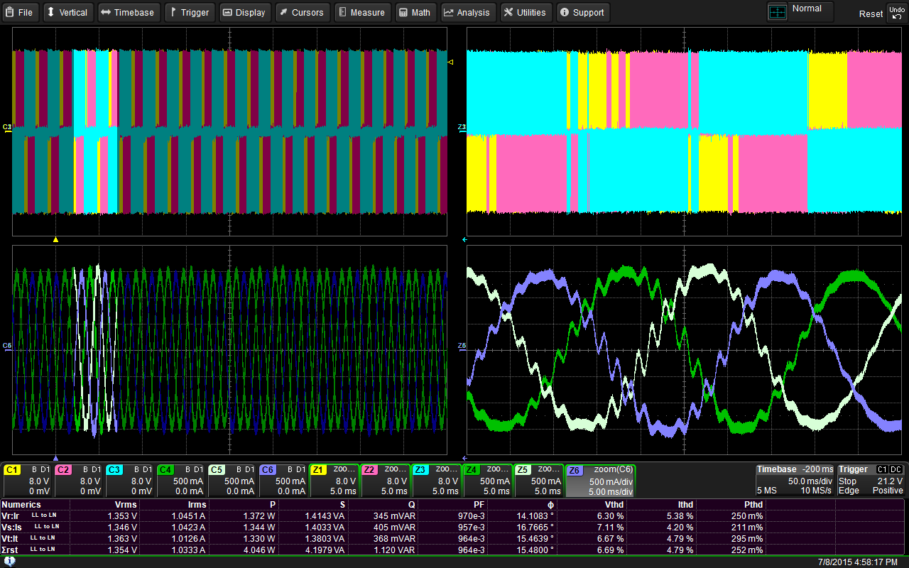
Measurement and spectrum display for up to 9 waveforms
The newly added table displays a detailed list of harmonic contributions of voltage, current, and power according to harmonic order. The table shows harmonic measurements and spectrum displays for up to nine waveforms (voltage, current, and power corresponding to each phase of a three-phase system). Users can perform this in both steady state (fixed frequency) and dynamic operating state (variable frequency).
The fixed frequency method provides specifications similar to those found in typical power analyzers (up to the 100th harmonic order). The symmetrical specification enhances the flexibility of variable frequency drive outputs up to 50 harmonic orders. The dynamic, variable frequency mode overcomes the limitations of individual frequency degree transformation (DFT) per cycle and the large PLL width of typical power analyzers, enabling software algorithms for harmonic analysis in high-dynamic drive output conditions where the drive frequency changes rapidly.

Comments
Related news
Teledyne LeCroy Launches Motor Drive Analyzer
2015.02.05by 명세환 기자
European Patent Applications Surpass 200,000 for the First Time… South Korea Maintains 5th Place, Led by Batteries and Telecommunications
According to the European Patent Office (EPO)'s 'Technology Dashboard 2025', European patent applications last year reached 201,974, surpassing 200,000 for the first time. Korean companies and inventors filed 14,355 applications, representing a 9.5% increase from the previous year and maintaining 5th place by country. Battery, digital communication, and semiconductor technologies led the growth, with Samsung ranking as the top EPO applicant for the second consecutive year and LG reaching 3rd place. The presence of major domestic cities such as Seoul, Suwon, and Yongin was also confirmed. It was also revealed that Korea's European patent strategy is expanding beyond individual technologies to span the entire industry.
2026.03.24by 명세환 기자
SK Telecom First Applies AI-Based Network Operations at Gwanghwamun K-Pop Concert
SK Telecom announced that it applied an AI-based network operation system for the first time at a large-scale K-pop concert held in the Gwanghwamun area of Seoul on March 21st, managing communication quality throughout the event. Mobile data usage during the three hours before and after the concert reached 12.15TB, approximately doubling compared to the same time slot the previous weekend. SK Telecom monitored traffic using the AI system 'A-One' in five-minute and 50-meter units to respond to potential overload situations, while also operating temporary communication facilities and on-site personnel in parallel. This case is interpreted as confirmation of the practical applicability of AI-based autonomous network operation in an environment where demand from dense events and foreign users increases simultaneously.
2026.03.23by 명세환 기자
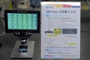
ETRI Develops 200Gbps Photodetector… Initiates Localization of Optical Receivers for AI Data Centers
The Electronics and Telecommunications Research Institute (ETRI) has developed a photodetector device that processes optical signals of approximately 200Gbps per channel for the first time in Korea. This device is a component that converts optical signals into electrical signals and determines the reception performance of AI data centers and 5G/6G communication networks. ETRI achieved bandwidth of 70GHz or higher and optical responsivity of 0.75A/W or higher, and integrated an indium phosphide lens on the rear of the chip to enhance optical reception efficiency and alignment convenience. The technology was presented at OECC 2025 and was recently published in the international academic journal 'Optics Express'.
2026.03.19by 명세환 기자
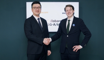
SKT and Ericsson Expand Joint Research on AI Networks… Preparing for 6G Beyond 5G Advancement
SK Telecom and Ericsson are expanding AI-based mobile network collaboration. On the 19th, the two companies signed a memorandum of understanding covering 5G advancement through 6G standardization, and agreed to undertake joint research and verification in the areas of AI-RAN, open and autonomous networks, security, and future communication technologies. This collaboration is interpreted as a move to enhance current 5G operational efficiency while preparing for a 6G environment where AI becomes embedded throughout the network. The scope also includes network operations automation, multi-vendor environment response, energy efficiency improvements, and review of communication-sensing fusion technology.
2026.03.19by 배종인 기자











