


[Op-Ed] Designing a Smart Power Supply by Adding an MCU
 Published2016.02.15 13:31
Engineering Manager, MCU08 Application Development Department
Microchip Technology Inc.
Intelligent Power Control
There are various power supply applications in the world, most of which simply require a current or voltage source to operate a system. With the increasing trend of these applications, it is necessary to regulate voltage and current through intelligent algorithms to enhance performance, reduce power consumption, and add new features to strengthen product competitiveness in the market. These applications include the following:

1) Maximum Power Point Tracking (MPPT) for photovoltaic power generation systems or energy harvesting
2) Battery charging, especially for more exotic chemical properties
3) LED lighting with dimming or daylight harvesting function
4) Fault Tolerance through Backup Power Systems
In each case, a microcontroller (MCU) that executes a certain level of intelligent algorithms is added to manage power more efficiently. Other power systems require intelligent functions simply to connect with people or other systems. Examples of these systems include SMbus power components on PC motherboards, LIN communication-connected lighting in vehicles, and power panels managed via Ethernet in large buildings. Simply adding communication functions to existing products increases their utility and value to some extent.
Existing smart power
The 'brute force' approach of many smart power systems is simply to add an MCU to an existing power system. This carries very low risk because the existing system performs the tasks and has a high level of understanding. The new part is simply the addition of intelligent functionality. This process typically involves circuitry for voltage, current, and temperature sensing, as well as other parameters such as the duty cycle or frequency of the existing power supply. Additional circuitry can be connected to control existing power supply functions, such as enable and voltage set points. Many SMPS ASICs already provide essential control inputs via I/O pins or I2C™ connections.
Various general-purpose MCUs, such as the PIC16F1939, can be connected to these ASICs and provide interfaces, commands, and controls to improve power supply functions.
Once connected to the power supply and verified, additional features can be rapidly developed using standard development tools such as MPLAB® X IDE and PICkit™ 3. Generally, with this method, the software development team does not need to fully understand the complexity of the SMPS design, as the SMPS team independently verifies the relevant parts of the system.
digital power supply
As part of efforts to reduce costs, there is a tendency to fully integrate the SMPS and MCU. One method that is actually effective is to use a high-performance MCU with a built-in high-speed sampling ADC. Using this type of device, a software-controlled, fully digital feedback system can be implemented. When performance is sufficiently high, very complex feedback algorithms can be implemented in software, while keeping the hardware very simple. This approach is very attractive, but the following points must be considered.
1) When problem solving requires the involvement of ADC and algorithms, traditional cut/jump debugging methods are not effective.
2) The software team must understand the performance and mathematical requirements of SMPS compensation. Sometimes, even very subtle code changes have a significant impact on stability.
3) Since the power requirements of the controller increase with MIPS, computationally intensive algorithms affect system efficiency.
If the system is not constrained by these limitations, excellent performance can be achieved through software.
Hybrid smart power
The hybrid approach lies between the simplicity of the 'indiscriminate' method and the fully digital method. In this method, a mixed-signal controller with built-in essential analog feedback peripherals and essential MCU functions are combined into a single integrated circuit (IC). One such device is the PIC16F753. The PIC16F753 integrates an operational amplifier, slope compensator, DAC, comparator, and pulse width modulation (PWM) controller into a single 14-pin microcontroller. Each of these peripherals is programmable and can be combined in various ways to implement different current-mode power supplies.
In addition, since settings can be configured in software, the environment settings can be dynamically changed according to the conditions of the power supply. For example, assuming a toy is in a standby state, it may be appropriate to drive the toy's power supply through a hysteresis controller equipped with a simple firmware feed-forward regulator. When the toy is activated, the power is rapidly reconfigured to a continuous current mode at another operating frequency to complete preparation for operation.
Since the entire power supply is controlled within the MCU's peripherals, all necessary sensing circuitry is part of the SMPS and is not added later in the design lifecycle. This simplifies the design and reduces the number of components. The firmware also provides several additional advantages to the power supply's operation without adding new components. The design process for the power supply is nearly identical to the conventional method. Each step is as follows:
1) Determine Power Supply Topology
2) Generate power and calculate component values
3) Configuration of internal peripherals (Line 20 of code)
4) Performance Verification and Compensation Network Adjustment
5) Writing Communication and Intelligent Interface Code
Since peripheral device setup and verification are performed by the power engineering team, Step 5 can be performed without detailed knowledge of the power supply.
design process
- Determination of power supply topology
- Create a model and calculate component values
- Configuration of microcontroller peripherals for power supplies
- Analog feedback loop adjustment
- Communication and intelligent code writing
General configuration
Most power supplies designed with the PIC16F753 show small deviations in typical SMPS configurations. This configuration is as follows.
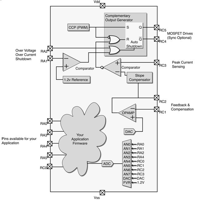
In this configuration, most peripheral devices are set to configure fixed-frequency current mode power supplies. COG stands for Complementary Output Generator, which generates a complementary output with a programmable deadband on the rising and falling inputs. CCP is configured to generate a programmable frequency rising edge. Comparator C1 generates a falling edge when the current exceeds the slope compensator output. CCP can be combined with C1 to generate the maximum duty cycle. Some topologies, such as Boost, Flyback, and SEPIC, require the maximum duty cycle. The OPA (Operational Amplifier, op amp) provides feedback and compensation.
In this configuration, the DAC provides the reference voltage to the operational amplifier, but if programming levels are not required, a fixed reference voltage (FVR) can also be used to provide the operational amplifier reference voltage. The slope compensator can be reset by a comparator or a COG. This is intended to attenuate a capacitor pre-charged to a level set by its input (in this case, the OPA), and operates using a programmable current sink. This power supply configuration is very easy to use. The following is an example of a boost power supply regulating current in an LED string.
Example of a Boost LED Power Supply
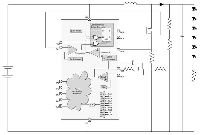
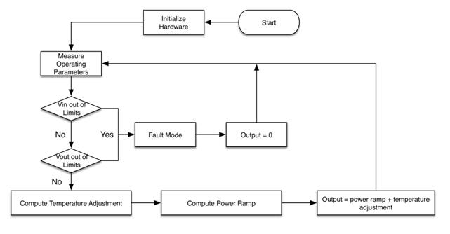
The hardware has been designed and tested. Intelligence can be easily added by implementing basic functions as shown in the example below.
LED Driver Flowchart
Max Power Point State Machine
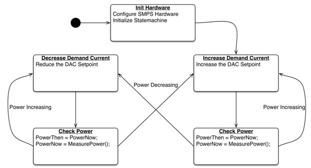
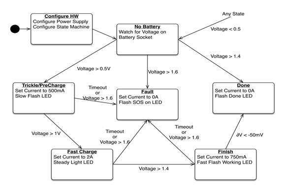
Battery charge status machine
conclusion
Adding an MCU to a power supply unit yields a much more powerful end result than using the device alone. This can be achieved by simply inserting an MCU into an existing SMPS design, building a fully digital SMPS with a high-performance dsPIC, or using a mixed-signal MCU that integrates MCU and analog SMPS functions into a single chip. More information regarding this can be found on the Microchip website (http://www.microchip.com/pagehandler/en-us/technology/intelligentpower/home.html).
The name and logo of Microchip, MPLAB, PIC, dsPIC, and PIC are registered trademarks of Microchip Technology Inc. in the United States and other countries. PICkit is a registered trademark of Microchip Technology Inc. All other trademarks mentioned in this text are the property of their respective owners.
관련뉴스
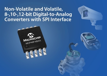
Microchip's DAC retains settings even when power is off
Microchip Technology has announced a new MCP48FXBXX device family and expanded its DAC (Digital-to-Analog Converter) product line.
2015.12.09by
[Feature] Visiting MCU Companies ⑥ Microchip: “Development Boards Will Be an Excellent Starting Point for IoT Design”
‘MCU 기업을 가다’는 이번에 전통적인 MCU 강자, 마이크로칩(Microchip Technology Inc.)를 소개한다. 마이크로칩은 세계적인 마이크로컨트롤러, 혼합 신호, 아날로그 및 플래시 IP 솔루션 전문기업으로, 제품 개발 위험이 적고 전체 시스템 비용이 낮으며 보다 빠른 제품 출시가 가능한 다양한 고객용 애플리케이션을 제공한다. 이에 마이크로칩 MCU8 부서 제품 마케팅 매니저, 웨인 프리먼(Wayne Freeman)과의 인터뷰를 통해 자세히 알아본다.
2016.01.25by 신윤오 기자
.jpg)
SalePoint Signs Multi-Year Partnership Agreement with AWS… Promoting Identity Security that Integrates Even AI Agents
Sailpoint has entered into a multi-year strategic partnership agreement with AWS and is moving forward with establishing an integrated governance system that manages both human and non-human identities together. The plan is to consistently manage access permissions in an environment where AI agents are increasing as work execution entities, while applying the principle of least privilege and automated policy enforcement. The two companies plan to jointly expand capabilities to manage the identities of various entities, including AI agents, within a single layer in the AWS environment. This collaboration is interpreted as a move to design security and governance together in corporate environments where AI adoption is expanding.
2026.03.26by 배종인 기자
.png)
Databricks Unveils Open AI Security Monitoring 'Lakewatch'
Databricks entered the security market on March 24 by unveiling LakeWatch, an open-source agentic SIEM. The core functionality of this product is to integrate and analyze security, IT, and business data in a single environment to support AI-based threat detection and investigation. The company explained that it reduces the limitations of existing security operations centers, which have had to forgo some data due to high cost structures, and enables large-scale data analysis and automation based on open formats and ecosystems. LakeWatch is currently offered as a private preview, with Adobe and Dropbox mentioned as early customers. Databricks also announced an expanded partnership with Anthropic as well as the acquisition of Antimatter and SiftD.ai.
2026.03.26by 배종인 기자











