



Smart door lock, how to use AA batteries for a long time
 Published2017.03.06 11:07
What power supply topology should be used to design a smart door lock's battery to last longer?
Power device topologies commonly used in smart door locks include linear regulators, boost (step-up), and buck (step-down).
The success of IoT (Internet of Things) devices depends on user convenience. Basically, user convenience means that electronic devices are easy to connect and control. The less maintenance required for these connected electronic devices, the better. Who would put up with the inconvenience of having to stop their electronic devices frequently to replace batteries?
The power supply of a smart door lock must support a wireless microcontroller (MCU) such as the SimpleLink™ Bluetooth low energy CC2640R2F solution, a motor driver such as the DRV8833 for opening and closing the door lock, and other peripherals such as LEDs. There are three ways to convert the voltage from the battery to the load: stepping down using a low dropout (LDO) linear regulator, stepping up using a boost DC/DC converter, or stepping down using a buck DC/DC converter.
Figure 1 shows a basic block diagram of a smart door lock using an LDO such as the TPS76625. Engineers choose LDOs because of their price. In most cases, the IC price of an LDO is lower than that of a buck (step-down) or boost (step-up) converter IC. However, linear circuits are less efficient and therefore shorten battery life.
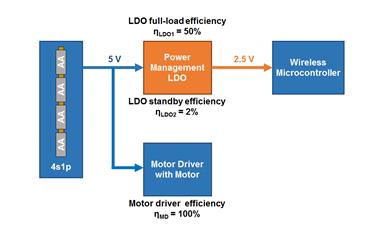
Figure 1: Block diagram of a smart door lock using LDO
Figure 2 is a block diagram using a boost converter such as the TPS61030. The four AA batteries are rearranged to support the boost topology for the motor driver, and the wireless MCU is connected directly to the batteries. Although this is very efficient, converting to high power using a boost converter for the motor driver leads to a higher power loss in absolute terms. Let's find a more efficient way.
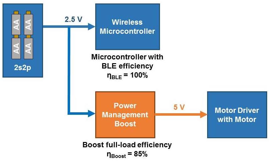
Figure 2: Smart door lock block diagram using boost converter
Figure 3 is a block diagram when using a buck converter. The efficiency figures are provided when using the TPS62745 ultra-low power buck converter. Using an ultra-low power converter can significantly improve the efficiency in the system's standby mode. The smart door lock is in standby mode most of the time except when the door lock is opened and closed.
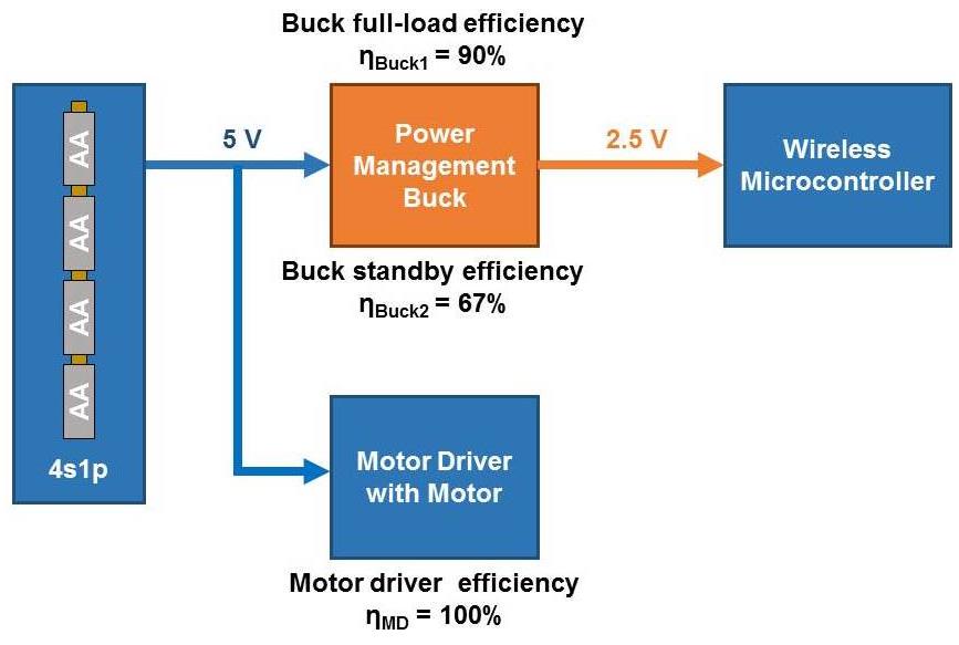
Figure 3: Smart door lock block diagram using buck converter
Figure 4 compares the battery life of each topology. This graph assumes that the door lock is opened and closed 12 times a day. As you can see from the graph, the battery life is proportional to the frequency of connection from the wireless MCU. The more frequently the wireless MCU connects to detect someone trying to open the door lock, the more power it consumes. When the interval between connections is 500ms, a battery life of 60 months (5 years) is possible using 4 AA alkaline batteries.
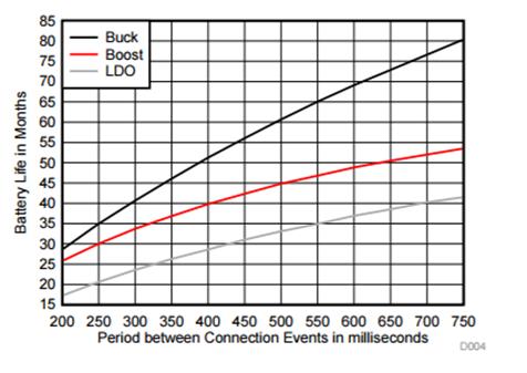
Figure 4: Battery life comparison with different power topologies
So far, we have briefly looked at different power topologies. The white paper “Extending Battery Life with Smart Door Locks” and the smart door lock reference design that provides 5+ years of battery life using 4 AA batteries are available on the TI website for more information.
Comments
Related news
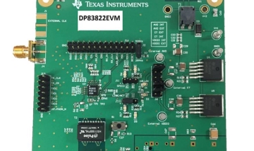
Why does Ethernet have to consume so much power?
"Why does Ethernet consume so much power?" is a question many people have. The rated effective power of 10/100Mbps Ethernet physical layer (PHY) transceivers is 110mW to 300mW or higher, and 10/100/1000Mbps gigabit Ethernet PHY consumes 450mW to 1,000mW or more of power. Typically, Ethernet PHY is one of the single components with the highest power consumption on the board and becomes an important factor in evaluating the thermal budget of closed systems. There are various low-power modes that can be applied to Ethernet to reduce overall system power.
2017.02.03by 신윤오 기자
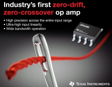
TI Launches Operational Amplifier for Industrial Applications
Texas Instruments announced the launch of an operational amplifier product that provides both zero drift and zero crossover technology. The OPA388 operational amplifier maintains high precision across the entire input range in various industrial applications such as test, instrumentation, medical and safety equipment, and high-resolution data acquisition systems.
2017.02.10by 김지혜 기자
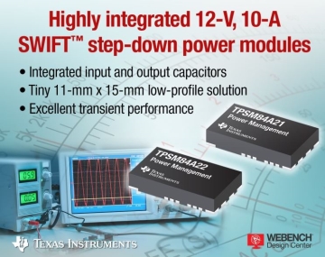
TI Launches Smallest Step-Down Power Solution
Texas Instruments has launched a 12V, 10A, 4MHz step-down power module set as a power management solution. The SWIFT TPSM84A21 and TPSM84A22 DC/DC modules integrate power MOSFETs, shielded inductors, input/output capacitors, and passive components in an ultra-compact, low-profile footprint. The new modules deliver less than 1% overshoot during transient conditions without requiring additional special magnetics or capacitors.
2017.02.16by 서아람 기자

Intel Unveils Next-Generation 'Core Ultra Series 3' and vPro Platform for Enterprise PCs
Intel has officially unveiled the "Intel Core Ultra Series 3" for next-generation enterprise PCs and the latest vPro platform, addressing a wide range of demands from enterprise notebooks to high-performance workstations.
2026.03.26by 배종인 기자

ROHM Launches ESD Protection Diode Compatible with High-Speed Interfaces of 10Gbps or Higher
Semiconductor specialist ROHM has developed the 'RESDxVx series' of ESD (electrostatic discharge) protection diodes capable of responding to next-generation high-speed data communication environments exceeding 10Gbps, simultaneously enhancing both signal quality maintenance required in high-speed interfaces and IC protection performance.
2026.03.26by 배종인 기자











