


USB Type-C, design is important for use regardless of cable
 Published2017.03.29 10:03
How to design incompatible cables so they don't damage your system.
A new type of USB is here. With the proliferation of USB Type-C ports on tablets, laptops, and smartphones, early adopters are facing problems due to the many UCB Type-C cables that are not compatible with the USB 3.1 specification.
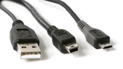
Most devices we use include some form of USB connectivity. This could be Type A or a micro/mini port. Because devices use a variety of connectors, cable confusion can occur. Previous generations offered low power consumption of less than 10W, so misusing cables wasn't a problem.
The USB Type-C standard brings two changes: 100W charging capability and a new connector design, as shown in Figure 2. This change in design necessitates an upgrade to USB cables. While numerous companies manufacture and sell USB Type-C cables, the sheer number of compatible and incompatible cables presents a significant risk of purchasing an incompatible cable. Some of the many cables are so out of specification that they can damage the systems they connect to.
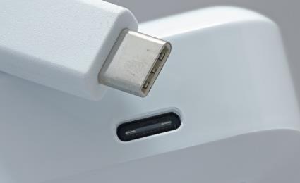
Therefore, robust power path protection must be implemented in system design to prevent damage to devices, regardless of the USB Type-C cable used. Implementing power path protection can prevent several common consumer issues, including connecting a defective cable to a working system or shorting out pins in close proximity due to moisture or debris inside the connector.
One way to implement these protection features is detailed in TI's USB Type-C Power Path Protection and Audio Accessory Support reference design.
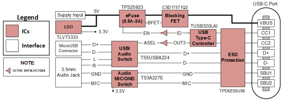
USB Type-C ports require multi-layered protection, particularly power and signal path protection. In this reference design, the TPD6E05U06 provides signal path protection for the CC1, CC2, D+, D-, SBU1, and SBU2 pins. This device provides International Electrotechnical Commission (IEC) 61000-4-2 Level 4 electrostatic discharge (ESD) protection by integrating six ultra-low loading capacitance transient voltage suppression (TVS) diodes on a single chip. The TPS25923 eFuse device and the CSD17571Q2 power MOSFET combine to provide up to 30 V of overvoltage protection, current limiting, and reverse current blocking for the power path. Finally, other important TUSB320LAI, TS5USBA224, and TS3A226AE manage USB cable orientation (USB Type-C is a reversible connector), operating role (DFP, UFP, DRP), and cable attach/detach.
These devices can also support analog audio accessories, providing both power and audio through a single USB Type-C port. Developers can also implement appropriate protection features in next-generation USB Type-C designs with the USB Type-C Power Path Protection Reference Design with Audio Accessory Support.
Comments
Related news
Why does Ethernet have to consume so much power?
"Why does Ethernet consume so much power?" is a question many people have. The rated effective power of 10/100Mbps Ethernet physical layer (PHY) transceivers is 110mW to 300mW or higher, and 10/100/1000Mbps gigabit Ethernet PHY consumes 450mW to 1,000mW or more of power. Typically, Ethernet PHY is one of the single components with the highest power consumption on the board and becomes an important factor in evaluating the thermal budget of closed systems. There are various low-power modes that can be applied to Ethernet to reduce overall system power.
2017.02.03by 신윤오 기자
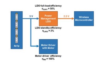
Smart door lock, how to use AA batteries for a long time
How should a smart door lock be designed with power device topology to maximize battery life? Generally, the power device topologies used in smart door locks include linear regulators, boost (step-up), and buck (step-down). The success of IoT (Internet of Things) devices depends on user convenience. Fundamentally, user convenience refers to easy connection and control of electronic devices. The less maintenance required for these connected electronic devices, the better. Would any user be willing to tolerate the inconvenience of having to stop electronic devices frequently for battery replacement?
2017.03.06by 김지혜 기자
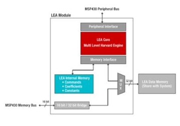
MCU processing speed improvement with LEA modules
Devices connected to the internet are highly diverse, ranging from industrial sensors used for factory process monitoring and intelligent fire detection systems to home Wi-Fi-connected thermostats and video doorbells, as well as barbecue thermometers. Many fields wish to add connectivity functionality, but implementation has been difficult due to hardware complexity and cost. Due to these constraints, it has recently become feasible with the emergence of user-friendly and cost-effective wireless connectivity modules and ICs.
2017.03.17by 김지혜 기자

Intel Unveils Next-Generation 'Core Ultra Series 3' and vPro Platform for Enterprise PCs
Intel has officially unveiled the "Intel Core Ultra Series 3" for next-generation enterprise PCs and the latest vPro platform, addressing a wide range of demands from enterprise notebooks to high-performance workstations.
2026.03.26by 배종인 기자

ROHM Launches ESD Protection Diode Compatible with High-Speed Interfaces of 10Gbps or Higher
Semiconductor specialist ROHM has developed the 'RESDxVx series' of ESD (electrostatic discharge) protection diodes capable of responding to next-generation high-speed data communication environments exceeding 10Gbps, simultaneously enhancing both signal quality maintenance required in high-speed interfaces and IC protection performance.
2026.03.26by 배종인 기자











