


Do you know how to optimize a voltage monitor?
 Published2017.04.20 09:58
Voltage monitors are required in various applications and systems. Voltage monitors have been monitoring analog voltage in digital circuits.
The TL7705 voltage monitor, first introduced by TI in 1983, consumes 1.8mA, is available in a plastic dual-inline package (PDIP), and is still in use. Recent products feature various capabilities, including ultra-low current (TPS3839), ultra-small package (TPS3831), dual channels (TPS3779/80), high accuracy (TPS3702), and multi-channel power monitoring (TPS386000). By selecting from these various product options, voltage monitor functionality can be optimized with simple circuit additions.
Depending on the application, there are some that require wider voltage hysteresis than provided by standard monitors. One way to increase hysteresis in adjustable monitors is to add a resistor between the output pin and the input resistor divider.
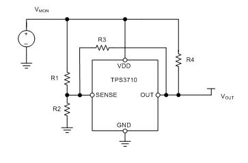
Figure 1: Adding a resistor to the TPS3710 for hysteresis control
In a typical configuration as shown in Figure 1, R1 and R2 set the threshold voltage and R4 is a pull-up resistor. By adding R3, hysteresis can be controlled by selecting an appropriate resistor, which provides a feedback path from the output to the divider voltage.
Since most systems use ground-based logic signals that require level shifting for communication, it is difficult to monitor negative voltages. To achieve the necessary level shift, an open-drain output must be used. The circuit diagram in Figure 2 shows how to use the TPS3700 with a level-shifted output from the negative rail to provide positive logic.
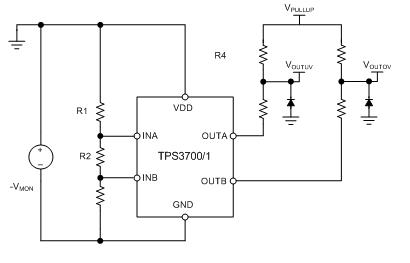
Figure 2: Additional TPS3700/1 configuration for negative voltage detection
The voltage monitored in Figure 2 is a negative voltage relative to ground. Overvoltage and undervoltage limits can be programmed using R1, R2, and R3 in the same way as with positive voltage. The open drain output of the TPS3700/1 is not dependent on VDD. That is, V(pullup) can be a positive voltage, and a positive ground-referenced logic voltage can interface with any MCU or processor.
Detecting negative voltage requires additional diodes and resistors at the output; however, to detect it using fewer components, the positive voltage is shifted by a resistor divider voltage so that the divided threshold voltage becomes positive relative to ground. The 4-channel TPS386000 monitor makes this easy by providing a reference voltage to which a resistor chain can be connected (Figure 3).
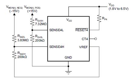
Figure 3: Detecting negative voltage using an external voltage reference
In Figure 3, the VMON(4,NEG) node represents a negative monitored voltage and the VMON(4,POS) node represents a positive monitored voltage. Negative monitoring is possible because the resistor divider is referenced to the VREF pin (1.2V output) rather than ground-based as in the positive channel. As shown in Figure 3, when the negative channel drops below -14.92V and the positive channel rises above 15.04V, the RESET output increases.
Most monitors typically require a voltage of about 800mV at VDD to provide an accurate output. If the voltage is lower than this, the monitor cannot control its internal circuitry to lower or raise the output. In that case, the output will rise to the pull-up voltage until the device pulls down. If this is not possible, a P-channel JFET can be added to keep the output low even when VDD is insufficient to power the monitor. Figure 4 illustrates this example.
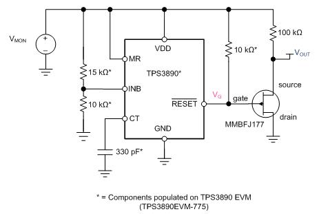
Figure 4: Preventing output voltage rise at low VDD by adding a JFET
In Figure 4, the normal output of the TPS3890 is labeled as VG . When VMON (monitored voltage) rises, the voltage of VG also rises briefly by about 0.5V. By adding a standard JFET configured as a source-follower, the voltage at the source can be tracked by subtracting the threshold voltage of the JFET from the voltage of VG . This causes a drop of about 1V between VG and VOUT , and eliminates the 0.5V rise in VG .
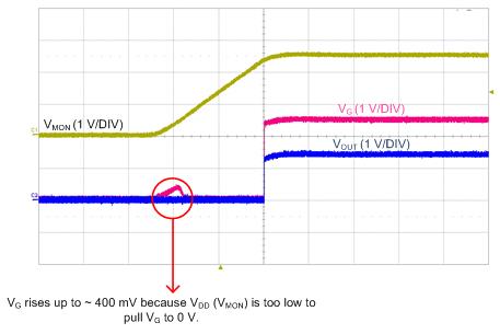
Figure 5: TPS3890 startup with and without JFET at output
Comments
Related news

TI Selects 16 Suppliers for Excellence Award
Texas Instruments (TI) announced the selection of 16 partners as recipients of this year's Supplier Excellence Award (SEA). This award is the highest-prestige honor TI bestows on its partners, recognizing companies that conduct business ethically while excellently meeting diverse requirements—including quality, environmental and social responsibility, technology, responsiveness, delivery, and cost—in products, services, and support. These 16 companies were selected from over 12,000 partners.
2017.04.06by 김지혜 기자
To make a small, cost-effective Bluetooth speaker
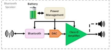
Multiple manufacturers are launching a variety of Bluetooth speakers, ranging from affordable speakers for basic systems to high-end premium models. To develop cost-effective products with competitive performance, design constraints such as solution size, component count, cost, efficiency, and battery capacity must be considered. The basic components inside a Bluetooth speaker can be seen in Figure 1. Batteries are essential in portable applications. The battery must be small and lightweight while providing maximum usage time using cells. The power management block supplies the necessary power to the rest of the circuit. Due to battery limitations, the voltage provided from one or two battery cells is very low. Therefore, a boost converter is required to increase the available voltage for the rest of the system.
2017.04.14by 김지혜 기자

What is important in a battery analysis system is the ADC
As portable devices have proliferated, battery-powered systems have become commonplace. Since battery defects occur frequently, it has become important to identify and replace battery defects early. Whether individual batteries used in mobile phones or battery banks for storing renewable energy, any battery defect can lead to system downtime. A precision analog-to-digital converter (ADC) is used as a key component in battery analysis systems that can assess battery health status. Depending on key specifications of the ADC such as speed, resolution, and latency, battery health status can be analyzed more accurately. Looking at the Randles lead-acid battery model in Figure 1, we can see how critical ADC performance is.
2017.04.18by 김지혜 기자

Intel Unveils Next-Generation 'Core Ultra Series 3' and vPro Platform for Enterprise PCs
Intel has officially unveiled the "Intel Core Ultra Series 3" for next-generation enterprise PCs and the latest vPro platform, addressing a wide range of demands from enterprise notebooks to high-performance workstations.
2026.03.26by 배종인 기자

ROHM Launches ESD Protection Diode Compatible with High-Speed Interfaces of 10Gbps or Higher
Semiconductor specialist ROHM has developed the 'RESDxVx series' of ESD (electrostatic discharge) protection diodes capable of responding to next-generation high-speed data communication environments exceeding 10Gbps, simultaneously enhancing both signal quality maintenance required in high-speed interfaces and IC protection performance.
2026.03.26by 배종인 기자











