


[MCU Q&A] 2. How do I connect EEPROM to MCU?
 Published2016.01.25 15:19
Masaru Sugai
STMicroelectronics (www.st.com)
1. What criteria should I use when choosing an MCU?
2nd: How do I connect EEPROM to MCU?
3: What is the difference between MCU and DSP?
Part 4: MCU Peripheral Components Selection Guide Power

< Q UESTION>
I want to connect an Electrically Erasable Programmable Read-Only Memory (EEPROM) to my MCU for use as external memory. I've heard there are many ways to connect it. Could you explain the different options?
< E XPLANATION>
For EEPROM, there are several different data access methods available, including Serial Peripheral Interface (SPI), Inter-Integrated Circuit (I2C), Microwire, and 1-Wire. Since many MCUs include SPI and I2C as peripheral functions, these two methods are mainly used. As an example, let's look at how to connect an EEPROM manufactured by STMicroelectronics (ST) to an STM8L series MCU. The I2C bus has only two bidirectional NMOS open-drain signal lines with pull-up resistors. Figure 1(a) shows an MCU connected to an M24xxx series EEPROM that uses I2C as its bus standard.
There are four types of SPI signal lines: SCK, MISO, MOSI, and SS. Figure 1(b) shows an example of an MCU connected to an M95xxx series EEPROM. Since the terminal names are different from the SPI signal names, the signal lines are indicated by the SPI signal names.
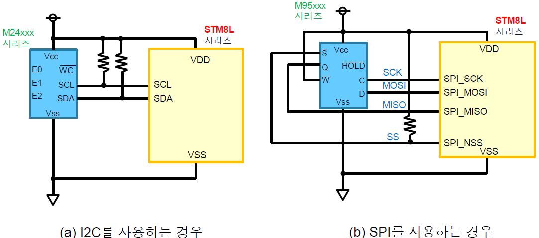
Figure 1. Connecting EEPROM to MCU
The MCU hardware performs basic communication control for both the I2C bus and the SPI bus, but additional software is required. The operation of the control software varies depending on the type of MCU used, so refer to the relevant user manual for details.
Interfacing the MCU and EEPROM
EEPROM data access methods can be divided into two types: serial bus method and parallel bus method. Since the parallel bus method requires the use of a large number of signal lines - for example, 8 bits for data signals and several bits (depending on the memory size) for address signals - the serial bus method is most commonly used. Common serial bus standards include SPI, I2C, Microwire, and 1-Wire. Most modern MCUs include SPI and I2C as peripheral functions, and one of them is mainly used as an interface for the MCU.
Address data and operation codes (op-codes) are exchanged through device-to-device communication. The op-codes are different for each EEPROM and include Write Enable/Disable, Register Read/Write, and Data Read/Write. These signals are controlled using MCU software.
I2C
I2C is a serial bus that supports a communications protocol developed by Philips. Each node is assigned a 7-bit address. Addresses for 16 nodes are reserved, but the rest (theoretically up to 112) can be connected to a single bus.
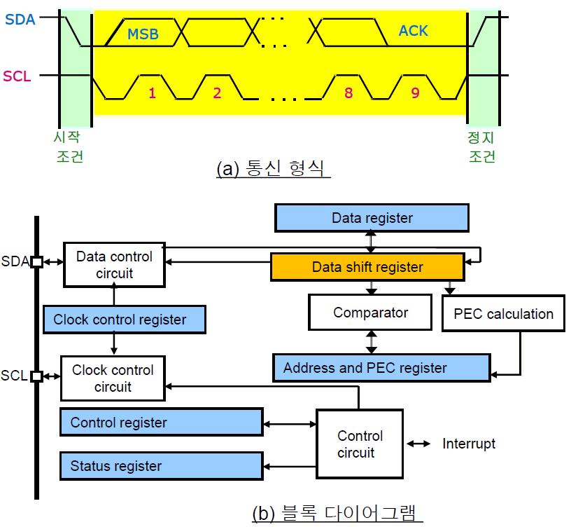
Figure 2. I2C module of STM8L series MCU
The I2C communication protocol basically follows the protocol used by Philips, but each MCU uses the protocol in a slightly different way. To understand this protocol more clearly, let's look at the I2C function of the STM8L series MCU as an example (Figure 2).
First, let's look at the communication flow (Figure 2(a)). The master device generates a clock signal (SCL), and when the start condition occurs, data transmission begins, and then when the stop condition occurs, data transmission ends.
The software installed on the master device generates both the start condition and the stop condition. When the MCU accesses the EEPROM, the MCU is the master device. It can recognize its own address and the universal call address in slave mode. Data and address are transmitted in 8-bit data units (1 byte) with the MSB first. The first byte transmitted after the start condition occurs contains the address. The address is always transmitted from the master device. After the byte consisting of 8 clock cycles is transmitted, the ninth clock pulse is generated. During this interval, the receiver must transmit an acknowledgment bit (ACK) to the transmitter.
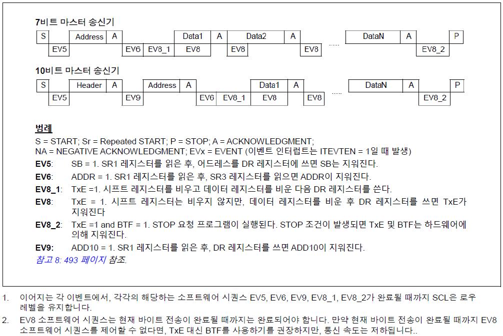
Figure 3. I2C communication protocol of STM8L series MCU
Next, let’s look at Figure 2(b). The figure shows the I2C module structure inside the MCU. Here, SDA is the data signal and SCL is the clock. The module contains a data shift register that shifts data bit by bit for output or input. The user can access the transmitted/received data through the data register. The module also has a built-in comparator that checks the address and PEC values. “PEC” stands for “Packet Error Check.” This is additional information used to check whether the data has been transmitted normally.
The communication speed is determined by the SCL frequency, which is 100 kbps in standard mode. However, STM8L provides a Fast Mode that can achieve a communication speed of 400 kbps.
Software is required to control the transmission sequence. The STM8L comes with a user manual with a sequence diagram as shown in Figure 3. By generating software that follows these sequences, we can perform communication operations.
Following the I2C procedure, you can communicate the address, data, and op-code (Write Enable/Disable, Register Read/Write, Data Read/Write) specified for each EEPROM.
SPI
SPI is a communication standard proposed by Motorola (now Freescale Semiconductor, Inc.). The physical function of SPI is the same as clock-synchronous serial communication. SPI uses four types of communication signals: clock (SCLK), master output/slave input (MOSI), master input/slave output (MISO), and slave select (SS). SCK is a synchronous clock that is output from the master device, MOSI and MISO are data signals synchronized to SCK, and SS is a slave recognition signal. When the master device outputs a low signal, the slave receives SS as an input, and if the state is low, the slave acknowledges the selection. This signal is similar to the chip select (CS).
The SPI communication protocol basically follows the protocol used by Motorola, but each MCU uses the protocol in a slightly different way. To understand the SPI function more clearly, let's take a look at the STM8L series MCU again (Figure 4).
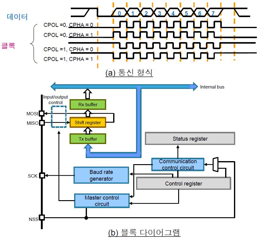
Figure 4. SPI module for STM8L series MCUs
As shown in Figure 4(a), the timing of data latching with respect to the clock phase can be determined by two parameters: clock polarity (CPOL) and clock phase (CPHA). The STM8L includes a built-in data shift register that shifts data bit by bit for output or input. Transmitted data is stored in the Tx buffer, and received data is stored in the Rx buffer. The CPU accesses the transmitted and received data through the Rx and Tx buffers.
The data transfer rate is determined by the SCK frequency. Since the STM8L has a built-in baud rate generator, this frequency can be set to any desired value. The maximum rate for the STM8L is 8MHz, but the specifications vary depending on the MCU used, so refer to the data sheet provided with the MCU in question.
Unlike I2C, SPI communication is basically the same as clock-synchronous serial communication, so SPI does not require the user to control the transmission sequence. One byte is transmitted at a rate of one bit per clock cycle.
You can communicate the address, data, and op-code (Write Enable/Disable, Register Read/Write, Data Read/Write) specified for each EEPROM in the same manner as synchronous serial communication.
Reference information
For a practical way to connect an EEPROM to an MCU, see:
(1) M24LR-Discovery: EEPROM (M24LR) and MCU (STM8L) are mounted on a 4.5cm × 9.0cm PCB. This board can perform communication operations between EEPROM and MCU via I2C. Circuit diagrams and information about this software are available for free download at:
http://www.st.com/web/en/catalog/tools/FM116/SC1444/PF253360?sc=m24lr04e-discovery
(2) Application Note AN2014: This document describes how to connect ST EEPROM to a standard MCU. You can also find detailed instructions for connecting using I2C, SPI, and Microwire. The PDF file can be downloaded for free from the following site:
http://www.st.com/web/en/resource/technical/document/application_note/CD00042024.pdf

Comments
Related news
Shipped 1 billion STM32 MCUs and over 500 million ST33 security MCUs
ST announced the shipment of 1 billion units of STM32, a general-purpose microcontroller based on ARM® Cortex® cores, and the achievement of 500 million units shipped for ST33, a secure microcontroller featuring the ARM SecureCore® SC300 processor.
2015.12.16by
[Planning] MCU Company ⑤ STMicroelectronics: "Highly integrated, low-power MCUs are perfect for IoT products, and we plan to expand into the low-end market in the future."
"Visiting MCU Companies" has this time sought out ST Microelectronics (hereinafter ST), renowned for its broad range of MCU offerings. ST possesses over 600 products that can be applied to diverse applications suited to the IoT era. Since the launch of STM32 in 2007, the company has currently moved into mass production of the STM32 F7 based on Cortex-M7. Additionally, ST plans to provide development environments free of charge to developers and hold training sessions. We meet with Manager Choi Kyung-hwa (photo), who oversees MCU operations at ST Korea, to hear about the secrets to competitiveness.
2016.01.11by 신윤오 기자

[MCU Q&A] 1. What criteria should I apply when selecting an MCU?
MCU Q&A ① Microcontrollers (MCUs) are essential components with diverse applications, ranging from rice cookers in our everyday lives to cutting-edge automobiles. But how much do we really know about MCUs? Do we simply select products based on the basic specifications that match the system we want to use? Or are you curious about how to connect an EEPROM to an MCU, what the differences are between MCUs and DSPs, or what the criteria are for selecting MCU peripherals? Starting today, e4ds News will run a four-part MCU Q&A series. We hope that information you have been curious about or may have overlooked will help you in selecting the right products.
2016.01.18by 신윤오 기자
.jpg)
SalePoint Signs Multi-Year Partnership Agreement with AWS… Promoting Identity Security that Integrates Even AI Agents
Sailpoint has entered into a multi-year strategic partnership agreement with AWS and is moving forward with establishing an integrated governance system that manages both human and non-human identities together. The plan is to consistently manage access permissions in an environment where AI agents are increasing as work execution entities, while applying the principle of least privilege and automated policy enforcement. The two companies plan to jointly expand capabilities to manage the identities of various entities, including AI agents, within a single layer in the AWS environment. This collaboration is interpreted as a move to design security and governance together in corporate environments where AI adoption is expanding.
2026.03.26by 배종인 기자
.png)
Databricks Unveils Open AI Security Monitoring 'Lakewatch'
Databricks entered the security market on March 24 by unveiling LakeWatch, an open-source agentic SIEM. The core functionality of this product is to integrate and analyze security, IT, and business data in a single environment to support AI-based threat detection and investigation. The company explained that it reduces the limitations of existing security operations centers, which have had to forgo some data due to high cost structures, and enables large-scale data analysis and automation based on open formats and ecosystems. LakeWatch is currently offered as a private preview, with Adobe and Dropbox mentioned as early customers. Databricks also announced an expanded partnership with Anthropic as well as the acquisition of Antimatter and SiftD.ai.
2026.03.26by 배종인 기자











