


[MCU Q&A] 4. MCU peripheral component selection guide - Power
 Published2016.02.15 12:05
Masaru Sugai
STMicroelectronics (www.st.com)
1. What criteria should I use when choosing an MCU?
2nd: How do I connect EEPROM to MCU?
3: What is the difference between MCU and DSP?
Part 4: MCU Peripheral Components Selection Guide - Power

< Q UESTION>
I'm trying to develop a system using MCU. What are some important considerations when designing MCU circuits and selecting components?
< A NSWER>
There are several types of power sources designed to fit MCUs: (1) Power sources that use dry batteries, including button batteries. These are the most familiar to us. (2) Power sources that are generated by converting a commercial 100VAC power source to AC/DC. These are used in many home appliances. (3) Power sources that are generated by converting the voltage of another DC power source, such as USB, to DC-DC. Recently, some wireless power systems are also available. When choosing a type of power source, you should consider the pros and cons of each.
The power supply for the MCU must have the following characteristics:
(1) Low noise and low ripple
(2) Stable voltage
(3) Ability to supply sufficient current
For systems using MCUs, the following must be considered:
(1) Low price (including operating costs)
(2) Portability: portable or stationary
(3) Maintenance (including durability and cost)
As you can see below, there are many articles on power types, so I will focus on the characteristics of power from the MCU's perspective.
DC-CC converter (http://ednjapan.com/edn/articles/1003/03/news103.html)
Constant current power source (http://ednjapan.com/edn/articles/1304/24/news008.html)
Power circuit control modes: voltage mode control, current mode control and ripple control (http://ednjapan.com/edn/articles/1003/03/news120.html)
Ripple and noise
When using a switching regulator, the switching action can cause ripple. Also, AC/DC conversion of commercial power can cause ripple due to residual AC components. In addition, the wiring can form an antenna and attract external noise. If you use USB as a power source, the PC connected to the USB can cause noise.
The size of the ripples that are maintained within the specifications of the MCU do not directly affect the operation of the MCU, but the high frequency components contained in them can generate noise. Since noise causes computational errors in the MCU, the power supply used for the MCU should reduce ripple and noise to the lowest possible level. On the MCU side, decoupling capacitors and choke coils are used to reduce ripple and improve noise suppression.
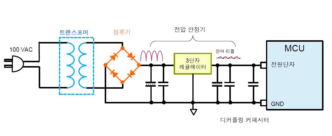
Figure 1 Power supply for MCU (3-terminal regulator)
Figure 1 shows a circuit that uses a transformer to step down the commercial power supply voltage and a three-terminal regulator to stabilize the voltage. Ripple may remain even after AC voltage rectification, so care must be taken when designing the circuit constants (capacitor values, wiring patterns, etc.).
The battery is the power source with the least amount of noise. The battery has no AC component and no connection to the external electrical environment, so there is no need to worry about ripple or noise. On the other hand, the noise generated by the MCU is relatively larger.
Voltage stability
One of the disadvantages of batteries is that their voltage decreases as energy is consumed. All MCU specifications specify a lower limit for the operating voltage, and operation is not guaranteed when the power supply voltage is outside the specified range. When the DC power supply voltage is converted from the commercial AC power, the voltage is always constant. Also, since the voltage is generated from a constant DC voltage source such as USB, there is no need to worry about voltage droop.
As a countermeasure against battery voltage reduction, the MCU needs to check the power supply voltage on its own and notify the external party (user) via display or sound when the voltage is reduced so that the battery can be replaced.
The MCU has a built-in power voltage monitoring circuit and AD converter, making it convenient to always check the power voltage.
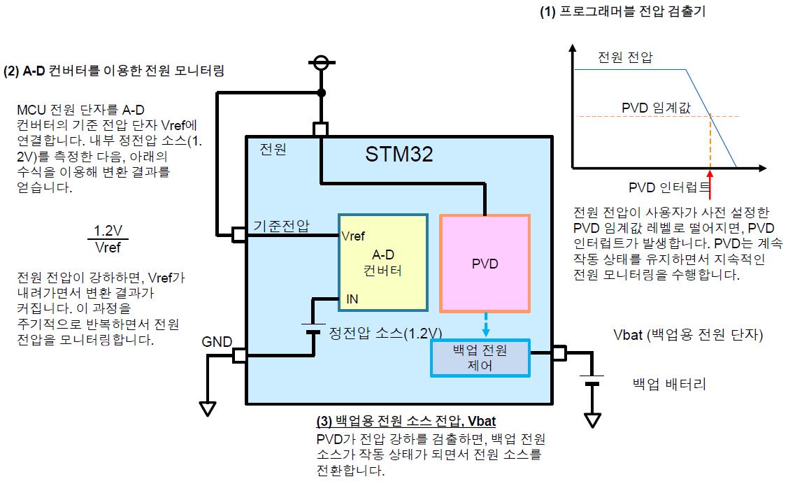
Figure 2 Power monitoring technique
Also, keep in mind that all power supplies are subject to voltage drops due to accidental events (in the worst case, power failure). Some MCUs have built-in backup power terminals that can be connected to an auxiliary power source to protect against such accidents. Users can take advantage of this feature for the same purpose.
Figure 2 shows these features built into the STM32F series from STMicroelectronics: (1) a programmable voltage detector (PVD), (2) a power supply test circuit using an AD converter, and (3) a backup terminal Vbat.
Power current capacity
If the capacity of the power supply supplying the current is not sufficient, the voltage will drop when a large current flows. Such voltage drop occurs when the output impedance of the power supply is not large enough. MCU users need to calculate the maximum current consumption of the MCU and design a power supply that matches the calculated result. The USB2.0 standard specifies the maximum current as 500mA. All current consumption of the target circuit, including the MCU, must be less than 500mA.
(However, a new USB standard has recently emerged called USB Power Delivery (USB PD). This system supplies up to 5A of current at 20V through a USB cable (up to 3A at 5V). See http://ednjapan.com/edn/articles/1505/21/news019.html.)
When using batteries, you need to calculate battery life using their capacity in mAh. Large capacity batteries—D or C and AA or AAA—are capable of accommodating large currents while supplying small currents.
Some new home appliances can use wireless power. Wireless power usually supplies relatively small current, so the inrush current can easily cause a voltage drop, preventing the MCU from starting up. This needs to be taken into account when designing the power circuit.
When calculating power capacity, keep these two things in mind:
(1) Inrush current (starting current)
When the power is turned on, a large current flows immediately. This current mainly charges the capacitor components in the electronic circuit. When the power is turned off, all the capacitors in the circuit are discharged. When the power is turned on, all the capacitors start charging, which causes a large current. As the capacitor charges, the current value decreases.
If you ignore the inrush current when designing the power capacity, the MCU may not start up due to voltage drop caused by large startup current.
(2) Current consumption by other components in the circuit other than the MCU
MCU datasheets provide current values that represent the current flowing through the MCU alone, excluding the current flowing through the GPIO interface and external circuits.
However, the power supply must accommodate not only the current flowing through the MCU, but also the total current passing through the GPIO and external circuitry. Therefore, the user (designer) must consider the maximum value of the total current of the system.
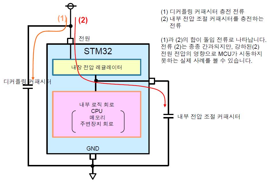
Figure 3 Inrush current
Examples of problems encountered during design
Finally, I would like to share with you my experiences with power-related issues.
(1) Incorrect circuit constant for power IC
As shown in Figure 1, power ICs such as 3-terminal regulators require capacitors. This MCU user used the recommended values for the decoupling capacitors of the MCU, but did not consider the capacitor values for the power ICs sufficiently. As a result, the MCU could not start up because it did not receive enough voltage. To obtain accurate circuit constants, you must read the specifications of the power IC as well as the specifications of the MCU.
(2) Starting the MCU with too small a current capacity
This user, who was developing a wireless power system, made a mistake in calculating the startup current, resulting in a current source capacity that was too small to start the MCU. This example is shown in Figure 3. When an MCU that uses an internal step-down method uses an internal voltage stabilizing capacitor, the charging current of this capacitor is also included in the startup current. This user calculated the power capacity considering only the charging current of the decoupling capacitor, but the actual startup current exceeded the designed value, which exceeded the allowable voltage drop.

Comments
Related news

[MCU Q&A] 1. What criteria should I apply when selecting an MCU?
MCU Q&A ① Microcontrollers (MCUs) are essential components with diverse applications, ranging from rice cookers in our everyday lives to cutting-edge automobiles. But how much do we really know about MCUs? Do we simply select products based on the basic specifications that match the system we want to use? Or are you curious about how to connect an EEPROM to an MCU, what the differences are between MCUs and DSPs, or what the criteria are for selecting MCU peripherals? Starting today, e4ds News will run a four-part MCU Q&A series. We hope that information you have been curious about or may have overlooked will help you in selecting the right products.
2016.01.18by 신윤오 기자

[MCU Q&A] 2. How do I connect EEPROM to MCU?
MCU Q&A ② Microcontrollers (MCUs) are essential components with diverse applications, ranging from everyday rice cookers to cutting-edge automobiles. But how much do we really know about MCUs? Do we simply select products based on basic specifications that match the system we intend to use? Or do we wonder how to connect EEPROM to an MCU, what the differences are between MCUs and DSPs, or what criteria to use when selecting MCU peripherals? e4ds News will run a four-part MCU Q&A series. We hope that information you may have been curious about or previously overlooked will help you in making product selections.
2016.01.25by 명세환 기자

[MCU Q&A] 3. What is the difference between MCU and DSP?
MCU Q&A ③ Microcontrollers (MCUs) are essential components with diverse applications, ranging from everyday appliances like rice cookers to cutting-edge automobiles. But how much do we actually know about MCUs? Do we simply select products based on basic specifications that match the system we want to use? Or do you not wonder how to connect an EEPROM to an MCU, what the differences are between an MCU and a DSP, or what criteria to use when selecting MCU peripherals? e4ds News will run a four-part MCU Q&A series. We hope that information you may have been curious about or previously overlooked will help guide your product selection.
2016.02.01by 신윤오 기자
.jpg)
SalePoint Signs Multi-Year Partnership Agreement with AWS… Promoting Identity Security that Integrates Even AI Agents
Sailpoint has entered into a multi-year strategic partnership agreement with AWS and is moving forward with establishing an integrated governance system that manages both human and non-human identities together. The plan is to consistently manage access permissions in an environment where AI agents are increasing as work execution entities, while applying the principle of least privilege and automated policy enforcement. The two companies plan to jointly expand capabilities to manage the identities of various entities, including AI agents, within a single layer in the AWS environment. This collaboration is interpreted as a move to design security and governance together in corporate environments where AI adoption is expanding.
2026.03.26by 배종인 기자
.png)
Databricks Unveils Open AI Security Monitoring 'Lakewatch'
Databricks entered the security market on March 24 by unveiling LakeWatch, an open-source agentic SIEM. The core functionality of this product is to integrate and analyze security, IT, and business data in a single environment to support AI-based threat detection and investigation. The company explained that it reduces the limitations of existing security operations centers, which have had to forgo some data due to high cost structures, and enables large-scale data analysis and automation based on open formats and ecosystems. LakeWatch is currently offered as a private preview, with Adobe and Dropbox mentioned as early customers. Databricks also announced an expanded partnership with Anthropic as well as the acquisition of Antimatter and SiftD.ai.
2026.03.26by 배종인 기자











