



[Contribution] How to design a flexible ADAS radar sensor
 Published2017.07.20 10:29
글: 스네하 나나카제(Sneha Narnakaje) / 텍사스 인스트루먼트
오토모티브 레이더 분석 및 프로세서 프로덕트 매니저
오토모티브 산업은 로보틱스 및 머신 비전에서 혁신과 기술 발전을 주도하고 있다. 자동차 제조사들은 다양한 기술들로 새로운 차량을 설계하며, 점점 커져가는 소비자의 욕구에 부응하고 있다. 이러한 트렌드는 ADAS(advanced driver assistance system)의 필요성을 불러 일으켰고, 안전과 편안함, 편의성, 에너지 효율성을 향상시켰다.
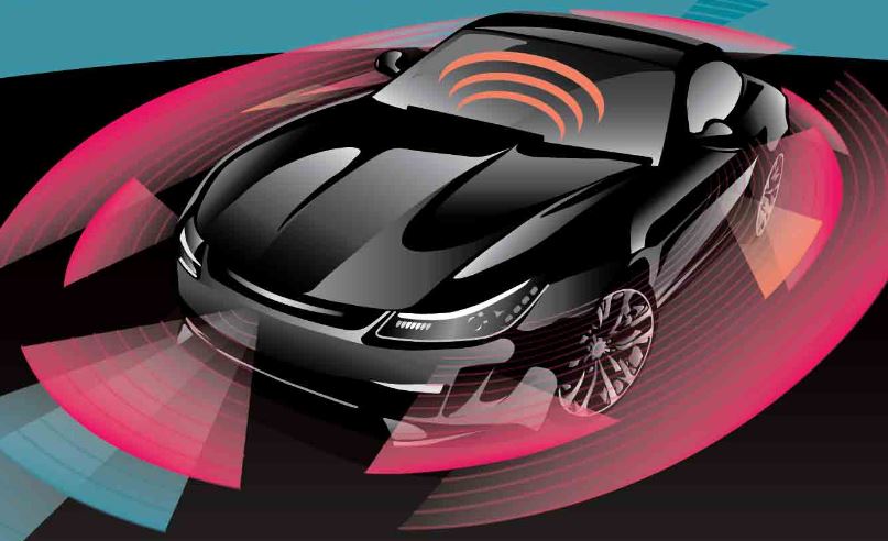
미국 고속도로 교통 안전국(National Highway Traffic Safety Administration) 같은 정부 기관들에 따르면, 미국에서는 3만명 이상, 전세계적으로는 130만 명 이상의 사람들이 해마다 교통사고로 죽는다. 이러한 교통사고의 94%는 사람의 실수와 관련 있는데 경고와 제동, 모니터링과 조향을 돕는 ADAS는 운전자의 실수를 줄여줄 수 있다.
오늘날의 많은 자동차들은 사각지대 및 차선 이탈 경고, 전방 및 후방 교차 충돌 경고, 자동 긴급 제동, 차선 유지 및 어댑티브 크루즈 컨트롤과 같은 기능들을 갖고 있다. 이러한 기능들은 브랜드마다 차별화되어 자동차 제조사의 수익원이 되고 있으며, 이제 일부 국가들에서는 2020년까지 모든 차량에 ADAS를 의무적으로 장착해야 한다.
자율주행의 토대, ADAS
안전 의식의 고양과 법규의 영향, OEM 업체의 안전 등급 등을 바탕으로, ADAS에 대한 수요가 급격히 늘어나고 있다. 리서치앤마켓(Research and Markets)의 글로벌 ADAS 시장 전망에 따르면, 2016년에 ADAS를 장착한 차량이 약 5천만 대 가량 출고되었고, 2022년에는 6천만 대에 이를 것이라고 한다. 리서치앤마켓의 또 다른 ADAS 시장 전망에 따르면, ADAS 부품의 출고 규모는 2016년의 2억 1,800만 개에서 2025년 12억 개로 늘어날 것이라고 한다. 일반적인 ADAS에는 첨단 프로세싱 및 통신 기능들과 더불어 다양한 센싱 기술들이 구현되어 있는데, 차량 시스템을 자동화하고 적응, 강화하여 안전과 주행 기능을 향상시킨다.
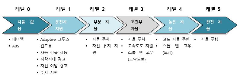
자동차 제조사들은 첨단 센싱 기술과 이미징/비전 기술에서 고성능 저전력 프로세서와 차량 내 네트워킹에 이르기까지 오토모티브 전자공학의 공급을 주요 반도체 공급사들에게 맡기고 있다. ADAS 컴포넌트의 성숙과 발전은 결국 반자율 및 자율 차량을 가능하게 할 것이다. 그림 1은 SAE 인터내셔널의 정의에 따른 자율주행의 6단계를 요약한 것이다.
자율주행 시스템은 차량 주변 정보를 포착하는 센서와 통신용 집적회로(IC), 센서 데이터를 분석하는 고성능 프로세서, 기계적 작동을 활성화하고 제어하는 마이크로컨트롤러(MCU) 등 다양한 컴포넌트들을 기반으로 한다.
센싱 시스템이 ADAS와 자율주행에 매우 중요한 이유는 차량에 지능을 더해주어, 주변 환경에 대해 정확하게 인식할 수 있기 때문이다. ADAS의 여러 이미지 센서들이 표준이 되고 있지만, 레이더와 레이저, 초음파, 적외선, 라이더와 같은 새로운 센싱 기술들도 모두 ADAS를 강화시켜 준다.
오토모티브 업계는 레이더 센서를 선호하는데, 이 센서가 플라스틱과 의복, 유리 같은 비금속 물체를 통과하고 안개와 비, 눈, 열악한 광 조건이나 눈 부신 광 조건 같은 환경 요소에 대체로 영향을 받지 않기 때문이다. 오토모티브 레이더 시스템은 물체 감지 거리에 따라 단거리, 중거리, 장거리 레이더로 나눌 수 있다. 또한 초단거리 레이더(USSR)도 주차 지원 시스템을 위한 ADAS 애플리케이션으로 새롭게 부상하고 있다. 사각지대 및 차선 이탈 경고와 같은 운전자 지원 기능들은 단거리 레이더(SRR) 시스템을 이용한다.
이러한 시스템은 SAE 인터내셔널 레벨 1에 해당되는데, 발광 다이오드(LED)나 스티어링 휠 진동을 이용해 운전자에게 보고하거나 경고하도록 되어 있다. 현재 SRR 시스템은 24-29GHz 주파수를 사용하고 있는데, 업계 전문가에 따르면, 저주파수에서의 출력 전력에 관한 법규로 인해 앞으로는 단계적으로 중단될 수도 있다고 한다.
어댑티브 크루즈 컨트롤과 자동 긴급 제동과 같은 운전자 지원 기능들은 장거리 레이더(LRR) 시스템을 사용한다. 이러한 시스템은 단순한 차량 제어 동작을 한다. 현재 LRR 시스템은 76-77GHz 주파수를 사용하고 있는데, 더 높은 수준의 자율 주행에는 더 나은 거리와 해상도가 필요해, 전방 레이더 시스템이 LRR과 새로운 중거리 레이더(MRR) 시스템을 조합할 경우 76–77GHz와 77–81GHz 주파수를 모두 사용하게 된다. 이보다 높은 레벨에서는 위험 요소를 감지하고 그 위험 요소(거리와 속도)의 속성을 측정하며, 고유의 속성(거리, 속도, 각도, 높이)를 가진 물체로 분류하는 등의 복잡한 시나리오들을 분석할 수 있는 레이더 센서들이 필요하게 될 것이다. 마지막으로 센서는 안전한 작동을 지원해야 한다.
TI의 AWR1x 밀리미터파(mmWave) 센서 포트폴리오는 개발자가 보다 안전하고 쉽게 주행할 수 있도록 한다. mmWave 센싱 아키텍처(그림 2)를 기반으로 하는 AWR1x 센서는 무선주파수(RF) 및 아날로그 기능과 디지털 제어 기능을 단 하나의 칩에 통합시키고 있다.
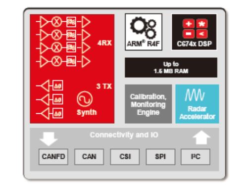

오토모티브 레이더 시스템 개발자는 온칩 BIST(built-in self-test) 기능을 이용해 기능의 안전 규격을 달성할 수 있다. 또한 이 포트폴리오에 속한 디바이스들은 하드웨어 가속기나 DSP를 통해 고객 프로그래머블 MCU와 단일 프로세싱 기능들도 집적하고 있다. 레이더 센서 설계를 AWR1x의 집적 수준까지 최적화시키면 크기와 전력을 줄일 수 있다.
복잡하고 극심한 도심 주행 시나리오들을 분석할 수 있는 초고정밀 오토모티브 레이더 센서는 76–81GHz 주파수의 전자기파를 이용해 그 센서의 시야에 있는 물체의 거리, 속도, 각도를 판단한다. 거리, 속도, 각도에 관해 몇몇 파라미터들이 레이더 시스템의 성능을 결정하는데, 그 중에서 분해능과 정밀도가 가장 중요하다. 분해능은 거리나 속도 또는 각도로 두 개 물체를 구분할 수 있는 능력인데, 나머지 두 개 변수는 이 물체들에서 동일하다. 예를 들어, 각도 분해능은 레이더 센서에서 같은 거리만큼 떨어져서 같은 속도로 주행하는 두 대의 차량을 구분할 수 있는 능력이다. 정밀도는 한 물체의 거리나 속도, 각도 계측의 정밀도를 의미한다. SAE 인터내셔널 레벨 2 이상에서는 SRR 애플리케이션에 대해 초고정밀 레이더 센서가 필요하다(50m).
오토모티브 레이더 시스템은 FMCW(frequency-modulated continuous waveform) 기법을 사용해 원거리 물체의 거리, 각도, 속도를 측정한다. FMCW 레이더에서, 처프 선형성(chirp linearity)은 한 물체의 거리 계측 정밀도를 말한다. 기존의 mmWave 센서들은 오픈 루프 VCO(voltage-controlled oscillator)에 기반한 처프 생성으로 처프 비선형성을 일으키기 때문에 거리 계측이 부정확하다. AWR1x mmWave 센서 포트폴리오도 FMCW 기법에 기반하고 있다. 이것은 폐회로 PLL를 이용해 0.01% 선형과 정밀한 처프를 가능하게 하기 때문에, 거리 정밀도가 향상되고 거리 분해능력이 높아진다. 처프 선형성은 잘못된 감지와 고스트 물체, 예를 들어 실제 목표물의 소산이나 부차적인 이미지를 방지해준다.
거리 분해능은 RF 대역폭과 상관관계에 있다. AWR1x 센서 포트폴리오는 단일 스윕에서 최대 4GHz까지의 처프 대역폭을 지원하므로, 5cm 미만의 거리 분해능을 가능하게 하는데 현재 시중에 나와 있는 mmWave 솔루션보다 3배가 더 정밀하다.
명징 속도란 비슷한 속도의 물체들을 구분하는 능력을 말한다. 특정한 거리 분해능과 최대 거리에서, 최대 속도를 높이려면 IF 대역폭이 높아져야 한다. AWR1x 포트폴리오의 고성능 레이더 프론트엔드는 15MHz의 IF 대역폭을 지원하므로, 250m 이상의 최대 거리와 최대 300kph까지의 속도가 가능하다. IF 대역폭과 위상 노이즈 성능을 조합하면 레이더 센서로 하여금 대형 물체 주변의 작은 물체들까지 감지하게 할 수 있다. 또한 고성능 프론트엔드에서 위상 응집성을 위한 내장형 20GHz 동기화 능력을 이용해 복수의 프론트엔드들을 단계화하여 극심한 도심 주행 환경에서도 1도 미만의 각 정밀도를 달성할 수 있고, 다리 밑이나 터널 같은 곳을 주행할 때에도 고도를 보다 잘 예측할 수 있게 해준다.
이 모두를 종합해 고도의 자율주행을 둘러싼 복잡한 시나리오들을 분석할 수 있으려면, 앞으로의 레이더 센서는 매우 정밀해야 한다. AWR1x 포트폴리오의 기능을 이용하면 매우 정밀한 센서를 설계할 수 있다.
가변 환경에 맞출 수 있는 다목적 인텔리전스
오토모티브 센서 제조사들은 SAE 인터내셔널 레벨 2 이상을 처리하기 위해 멀티모드 레이더 시스템으로 눈을 돌리고 있다. 멀티모드 레이더 시스템 구성에서 센서는 하나의 센서 모듈에서 MRR과 LRR 구성을 모두 지원되도록 설계되었으므로, 자동차 제조사들은 원가를 크게 절감할 수 있다. 이제는 각각의 구성을 지원하는데 두 개의 센서 모듈이 각기 따로 필요하지 않기 때문이다. 멀티모드 레이더 시스템 설계는 mmWave 기술 공급자에게 사용 편의성, 유연한 처프 구성, 모니터링 등과 같은 특정 요건들을 부과한다.
AWR1x 포트폴리오는 BIST 엔진을 집적하여 처프 생성 파라미터들을 실시간으로 로컬 제어한다. 이 엔진은 로컬 디지털 서브시스템이나 외부 호스트 프로세서의 비실시간 메시징을 통해 다이내믹 처프 구성을 지원한다. BIST 엔진은 온도와 노후화 같은 변화하는 환경 조건에 맞춰 센서를 자동으로 적응시킨다. 이를 통해 출력 전력과 게인 같은 RF 파라미터에서 드리프트의 셀프 캘리브레이션을 가능하게 해준다. 또한 BIST 엔진은 지속적으로 RF와 주요 RF 성능 파라미터에 관한 아날로그 서브시스템을 모니터링 함으로써 안전을 강화한다.
기존의 mmWave 센싱 기술이 실시간 베이스밴드 아키텍처를 이용했다면, 이 AWR1x 센서는 새로운 복합 베이스밴드 아키텍처를 통해 시스템 레벨의 성능상 이점들을 구현하고 있다. 오토모티브 레이더 센서는 범퍼 너머에 탑재되기 때문에, 센서가 범퍼 반향을 정밀하게 계산할 수 있다면 범퍼 시그니처를 기억해 부팅을 할 때마다 캘리브레이션을 할 수 있다. AWR1x 포트폴리오는 범퍼 시그니처의 빈도가 낮기 때문에 실제 베이스밴드 아키텍처에서는 거의 불가능한 범퍼 반사의 제로 거리 등급과 범퍼 반향의 위상을 이용해 가까운 물체를 더 정밀한 계산을 할 수 있다. 또한 복합 베이스밴드 아키텍처를 이용해 이미지 밴드를 모니터링 하고, 진짜 물체에 대한 모호성 없이 다른 전파 방해 레이더들의 간섭까지 탐지하여 탄탄한 레이더 센서 설계도 가능하다.
진정한 단일 칩을 통해 가능해진 소형 저전력 레이더 센서
자율주행이 현실화되면서 레이더 센서 요건들은 전력, 크기, 비용, 거리, 정밀도에 의해 좌우될 것이다. SAE 레벨 2 이상의 자율주행 시스템에는 현재의 솔루션보다 훨씬 더 많은 레이더 센서가 필요하며, 오늘날의 하이엔드 차량들은 멀티칩 단일 레이더 시스템을 가지고 있다. 복수의 개별 컴포넌트들을 사용한다고 가정했을 때, 이러한 레이더 시스템은 크고 부피가 커서, 더 작고 저전력이며, 비용 효과적일 필요가 있다. 앞으로의 자율주행 시장 수요에 적응하려면 이 센서들은 소형화, 최적화되어야 한다.
현재 시중에 나와 있는 레이더 시스템들 중 일부는 단일 칩 솔루션이라고 하지만, 실제로는 그렇지 않다. 현재의 솔루션들은 여전히 많은 수의 컴포넌트들을 필요로 한다. 개별 칩의 수를 세 개에서 하나로 줄였지만, 레이더 데이터를 처리하려면 외부 MCU나 DSP를 갖춘 트랜시버가 필요하다.
CMOS 기술 덕분에 TI는 MCU 및 DSP 기능을 갖춘 인텔리전트 레이더 프론트 엔드를 AWR1x 단일 칩 포트폴리오에 집적시켰다. 프로세싱이 이 프론트엔드에 병합되어 있어 레이더 시스템의 크기와 폼 팩터가 50%까지 줄어들었다. 이것은 복수의 레이더 시스템을 효율적으로 탑재할 수 있게 해준다. CMOS 기술과 동급 최강의 전력 관리 기법은 AWR1x 센서의 저전력을 가능하게 해주며, 오토모티브 업계의 에너지 효율 전기차 개발에 있어 필수적인 요소이다. 설계자는 이제 더 경제적이고 가벼운 하우징을 선택할 수 있기 때문에, 저전력은 비용상의 이점도 있다. 또한 AWR1x 센서가 더 높은 주변 온도를 견디고 센서의 신뢰도도 높일 수 있게 해준다.
이러한 모든 기능은 대량 생산이 가능한 신뢰할 수 있는 패키지로 제공될 때에만 고객에게 도움이 된다. AWR1x mmWave 포트폴리오는 오토모티브 친화적인 FC-BGA(flip-chip ball-grid array) 패키지로 제공된다. 이 FC-BGA 패키지 솔루션은 신뢰할 수 있는 전기적, 기계적, 열량적 성능을 발휘하며, 방출을 위한 쉴딩을 없애고, 인터커넥트를 보호하기 위한 칩 바닥면을 보호하는 물질, 언더필의 필요성을 없앰으로써, mmWave 센싱 기술에 사용되던 기존 패키지에 비해 비용 면에서 유리하다.
AWR1x mmWave 포트폴리오가 지원하는
ADAS와 바디 및 섀시, 내실 애플리케이션들
TI의 AWR1x mmWave 포트폴리오는 ADAS, 바디 및 섀시, 내실 등의 애플리케이션들에서 고정밀 센싱 애플리케이션을 지원한다. 이 포트폴리오는 고성능 레이더 프론트엔드(AWR1243)에서 단일 칩 레이더 솔루션(AWR1443과 AWR1642)까지 다양하다. 표 1은 AWR1x 포트폴리오의 센서들 각각의 주요 특징을 요약한 것이다.
세 개의 디바이스로 이루어진 이 포트폴리오는 USRR, SRR, MRR에서 LRR과 이미징까지 다양한 ADAS 레이더 센서 구성들을 지원하고 있다. 또한 모든 레이더 프로세싱이 엣지에서 발생하는 스마트 센서 아키텍처를 가능하게 한다. 위성 센서 아키텍처에서는 레이더 센서가 CAN-FD를 통해 물체 데이터를 중앙 프로세서로 보내 추가 프로세싱과 센서 융합을 한다.
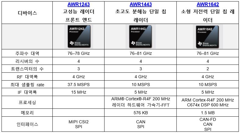
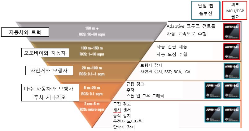
그림 3은 AWR1x mmWave 센서를 레이더 단면적(RCS)의 정의대로, 감지 대상 물체의 거리와 유형에 따라 ADAS, 바디 앤 섀시, 내실 등의 애플리케이션으로 분류한 것이다.
결론
개발자가 자신의 설계의 필요에 적합한 솔루션을 선택할 수 있으므로, 센서는 이 시장에서 매우 특별하다. 이와 같은 집적의 정도와 작은 풋프린트는 설계자가 기존 애플리케이션에 새로운 기능들을 추가할 수 있도록 해준다. 시장이 ADAS와 자율 차량에 적응함에 따라, TI의 mmWave AWR1x 센서 포트폴리오는 이에 필요한 유연성을 발휘할 수 있을 것이다.
상세 정보: 이 포트폴리오에 관한 자세한 정보는 www.ti.com/mmwave를 참고하면 된다.

Comments
Related news
[Planning-Autonomous Vehicles①] Domestic Technology 'Cannot Stand Alone' - Strategic Collaboration Ecosystem Must Be Established
The most striking aspect of the 2017 Seoul Motor Show that concluded last week was the first-time participation of NAVER, a leading domestic IT company. While IT companies developing automobiles is no longer an unfamiliar sight, the appearance of a leading domestic IT company at Korea's representative auto show holds significant symbolic meaning for the automotive sector. NAVER became the first domestic IT company to receive temporary road-driving approval from the Ministry of Land, Infrastructure and Transport for autonomous vehicles. Presenting a Level 3 autonomous vehicle, NAVER is developing autonomous vehicles as part of environmental implementation with 'living environment intelligence' as its technological direction. Prior to this, Hyundai Motor presented a Level 4 vehicle where the system can safely operate without driver intervention. Hyundai achieved autonomous driving by adding only minimal sensors such as radar and LiDAR to sensors already applied in mass-production vehicles.
2017.04.10by 김지혜 기자
[Interview] Domestic LiDAR Technology Capable of Multi-Channel, 360-Degree Scanning
In autonomous driving, sensors play a role in recognizing surrounding situations. Among them, LIDAR is referred to as the 'eyes' of autonomous vehicles and is a sensor that can cover blind spots invisible to radar. However, it faces the challenge of needing to reduce costs in order to commercialize Level 3, where vehicles can operate partially autonomously. Han-Young Lee, Principal Researcher at the Smart Sensor Research Center of the Korea Electronics Technology Institute (KETI), explained, "LIDAR used in autonomous vehicles must respond to accidents that can suddenly occur in fast-moving cars, so the number of channels and scan speed are important factors."
2017.04.12by 김지혜 기자
[Feature - Autonomous Vehicles ②] Radar IC Market Seeing More 'Players'; Will Competition Heat Up Among Semiconductor Companies?
If there is a technology where the phrase "dreams have become reality" fits best, it would surely be autonomous vehicles. You summon a car and it comes running on its own, then drives to your destination by itself. Autonomous vehicles recognize and avoid obstacles during driving while providing various convenities and information to the owner. While full autonomy commercialization will take some time, so-called "semi-autonomous driving" technology is becoming increasingly sophisticated. Nowadays, advertisements for automobiles equipped with autonomous driving functions are easy to see, bringing the technology deep into our daily lives. This publication will serialize an autonomous vehicle planning series over the course of 11 installments. Beginning with autonomous vehicle industry trends, we will cover semiconductor components such as radar, lidar, and camera sensors, as well as communications, precision mapping, software platforms, artificial intelligence, security, and K-City services. We appreciate your continued support and interest. <Editor's Note> The radar IC market, one of the key sensors for autonomous driving, is heating up increasingly.
2017.04.17by 신윤오 기자
[Planning - Autonomous Vehicles ③] Camera, Lidar “Cars finally have eyes”
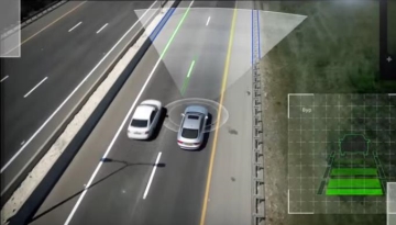
As commercialization of Level 3 autonomous driving technology begins, interest in advanced driver assistance systems is also increasing. ADAS systems serve as a foundation for autonomous vehicles, and while they initially primarily functioned to inform drivers of road conditions through notifications, they have recently advanced to the level of automatically controlling the steering wheel, brakes, and other components. The Genesis EQ900 is equipped with advanced driver assistance systems (ADAS) including Advanced Smart Cruise Control (ASCC), Blind Spot Detection (BSD), Autonomous Emergency Braking (AEB), Driver Attention Alert (DAA), Smart High Beam (SHBA), and front seat pre-active seatbelts. The new i30 wagon incorporates ADAS technologies such as Adaptive Cruise Control (ACC), AEB, and Lane Keeping Assist System. For these ADAS systems to operate, detection through cameras, lidar, and radar sensors is essential. When examining ADAS system installation by vehicle type, except for some small vehicles, either cameras alone or a combination of radar and stereo cameras are applied. Cameras can cover a range of up to 100m ahead, surround view, and rear areas. They function in a role that provides intuitive assistance to drivers by enabling actual visual observation. For autonomous driving, a minimum of 5 or more camera sensors per vehicle must be installed to achieve 360-degree full coverage detection.
2017.04.24by 김지혜 기자
[Automotive Video Coverage] NXP Unveils Radar-Dedicated Chipset Combining Three Functions into One
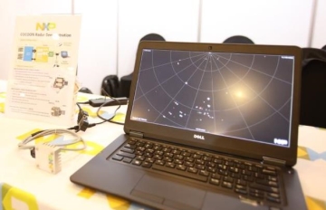
Participating in Automotive Innovation Day 2017, held on the 5th and hosted by Automotive Electronics, NXP demonstrated a vehicle radar solution implemented with a radar-dedicated chipset. The 'TEF810X', commonly known as Dolphin, employs RFCMOS technology for ultra-compact system design. This chip integrates four key functions: radar signal generation, transmission, reception, and digitalization. It operates at a 77GHz frequency to deliver high-resolution performance.
2017.07.17by 김지혜 기자











