


Optimizing Power Supply Efficiency Using a 6-Phase Buck Controller
 Published2021.03.17 15:25
LTC7852/LTC7852-1 듀얼 출력 벅 컨트롤러,
최대 240A 이르는 6위상 컨버터 설계 지원
통신, 서버, 컴퓨팅 시스템에 사용되는 ASIC, FPGA, 프로세서는 12V에서 곧바로, 또는 중간 버스로부터 1V 및 1V 이하의 전압을, 때때로 최대 200A가 넘는 부하 전류로 발생시키는 코어 전원장치가 필요하다.
이들 전원장치는 엄격한 효율 및 성능 요건을 충족해야 하며, PCB 풋프린트 또한 작아야 한다. 아나로그디바이스(ADI)의 6위상 듀얼 출력 벅 컨트롤러, ‘LTC7852’ 및 ‘LTC7852-1’은 이러한 요구를 충족한다.
두 컨트롤러는 내부 게이트 드라이버를 사용하지 않는다. 각각의 위상이 전원 블록과 DrMOS, 또는 외부 게이트 드라이버와 디스크리트 MOSFET를 인터페이스하는 PWM 출력을 발생시킨다.
DrMOS 디바이스는 게이트 드라이버와 MOSFET을 통합하여 솔루션의 소형화와 효율화에 이바지하며, 통상 12V 입력 전압으로 설계된다. 외부 게이트 드라이버와 MOSFET은 우수한 열 성능과 더 높은 입력 전압으로의 동작을 보장한다.
LTC7852는 sub-mΩ DCR 검출 아키텍처를 사용해서 0.2mΩ에 불과한 DCR 값으로 정확한 전류를 검출할 수 있어 전도 손실을 크게 낮춘다. LTC7852-1은 자체적인 전류 검출 신호를 제공하는 DrMOS 디바이스와 함께 쓰도록 설계됐다.
각각의 출력은 차동으로 검출된다. 출력 범위는 0.5V~2.0V이고, 총 레귤레이션 정확도는 ±0.5%다. LTC7852와 LTC7852-1은 입력 전압이 아니라 외부 5V 전원을 사용해서 바이어스 하므로, 컨버터의 입력 전압 범위를 제한하지 않는다. 스위칭 주파수 범위는 250kHz~1.25MHz이고, 최소 온(on) 시간은 40ns다.
두 컨트롤러는 PHCFG 핀을 사용해서 2개의 출력을 3+3, 4+2, 5+1 위상 구성 중에서 선택할 수 있다. 3+3 구성의 경우, 2개 출력을 병렬로 연결해서 최대 부하 전류가 240A에 이르는 6위상 컨버터를 달성할 수 있다.
2개의 3위상 컨트롤러나 3개의 2위상 컨트롤러가 아니라 1개의 6위상 컨트롤러를 사용함으로써 설계와 배열을 크게 간소화할 수 있다. 2개 사용 시 최대 12위상 동작을 달성할 수 있다. LTC7852는 5mm×6mm GQFN 패키지로, LTC7852-1은 4mm×5mm QFN 패키지로 제공된다.
◇ 6위상 고효율 코어 전원
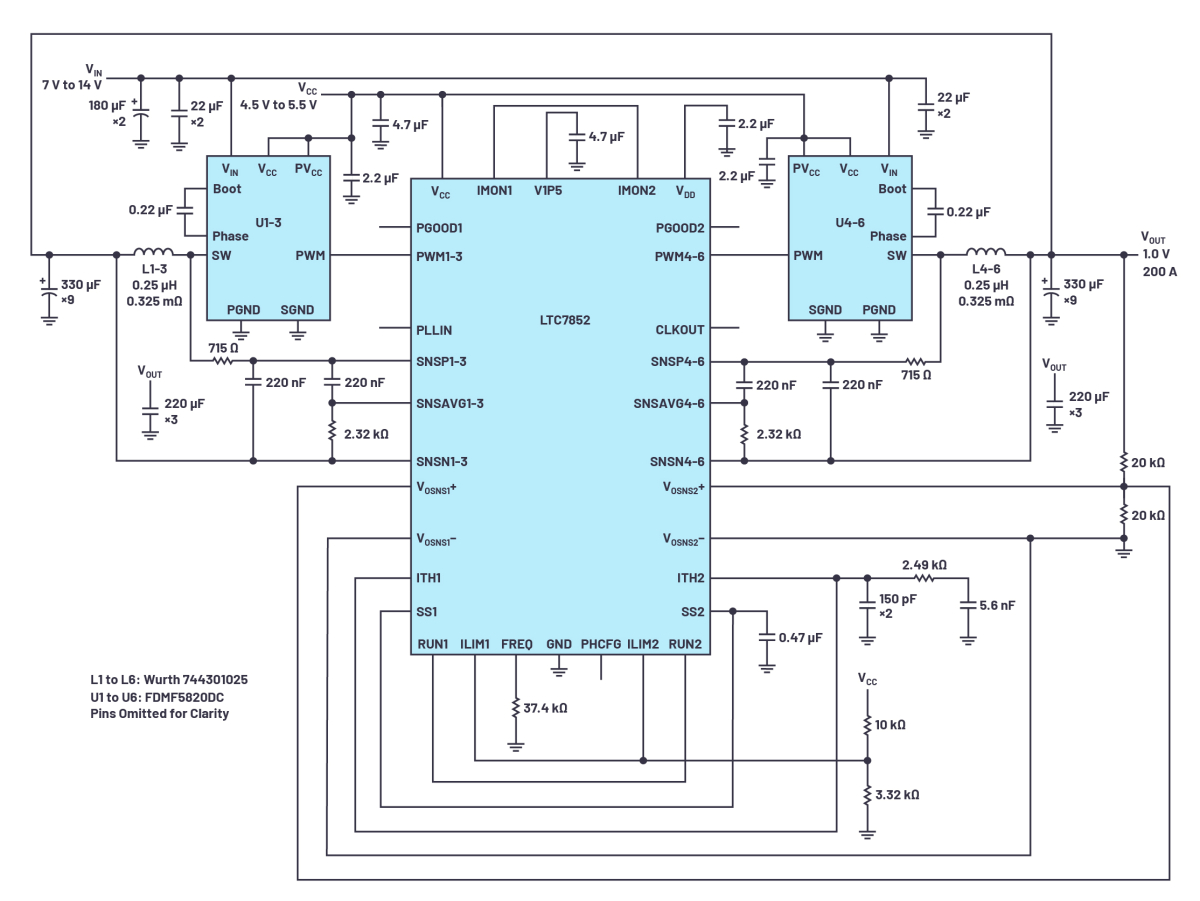
FDMF5820DC DrMOS를 함께 사용한 회로도
스위칭 주파수(FSWITCH)는 400kHz다
[그림 1]은 LTC7852를 사용한 6위상 1.0V/200A 컨버터다. 400kHz 스위칭 주파수와 12V 입력으로 동작하며, 각 위상의 전원 스테이지는 5mm×5mm 크기의 DrMOS와 정격 DCR이 0.325mΩ인 0.25μH 페라이트 인덕터로 이뤄진다.
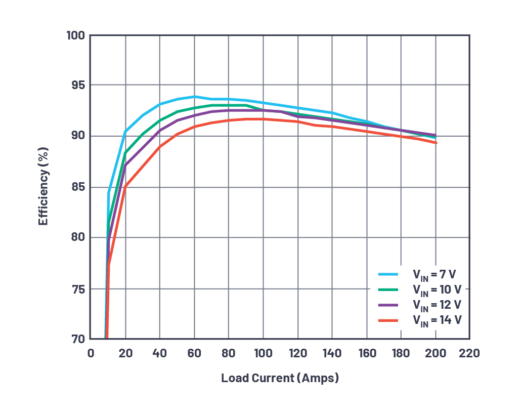
그림 1 회로의 효율 곡선

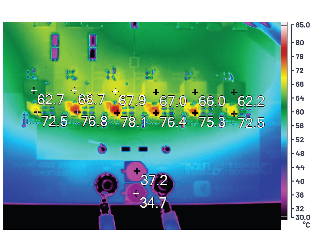
200LFM 에어플로일 때 그림 1 회로의 열화상
[그림 2]는 결과적인 총 부하 효율이 90.0%임을 나타낸다. [그림 3]은 풀 부하로 200LFM 에어플로를 사용하면, 핫스팟의 온도가 상온에서 78℃임을 보여준다. 빈틈이 없는 전류 공유로 인해, 인덕터 간에 온도 차이는 6℃ 미만이다.
◇ Sub-mΩ DCR 검출
LTC7852는 고유의 피크 전류 모드 sub-mΩ DCR 검출 아키텍처를 사용해서 전류 검출 신호의 신호대 잡음비(SNR)를 개선한다. 인덕터 상의 DCR 검출 필터는 SNSP/SNSN 핀에 증폭된 AC 신호를 제공하며, 일차 필터에 종속적으로 연결된 이차 필터가 SNSP/SNSAVG 핀으로 DC 신호를 제공한다. LTC7852는 DC 신호를 증폭하고 AC 신호와 합해서 신호를 복원하는데, 복원된 신호는 원래 신호의 5배다. 따라서 0.2mΩ 정도의 DCR 값으로 깨끗하고 안정적인 동작이 가능하다.
◇ 출력 전류 모니터링과 과전류 보호
LTC7852의 IMON1 핀과 IMON2 핀은 해당 채널의 부하 전류에 비례하는 신호를 발생시키고 V1P5 핀으로 참조된다. 이 신호는 전원장치 모니터링이나 ADC와 MCU의 부하 감지에 사용된다.
사이클 대 사이클 전류 제한은 피크 전류 모드 아키텍처의 근본적인 이점이다. 히컵 모드 전류 제한이 추가적인 보호를 제공한다. 과전류 결함이 32사이클 이상 동안 지속되면, 소프트 스타트 커패시터로 설정된 시간 길이 동안 컨버터가 스위칭을 중단한다. 이 간격이 종료되면 소프트 스타트와 함께 스위칭이 재개된다.
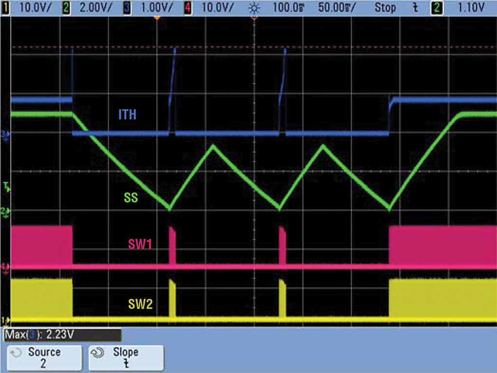
[그림 4]에서 보듯이, 결함 시에는 컨버터가 비교적 짧은 간격으로 스위칭하면서 MOSFET나 인덕터 상에서의 열 스트레스를 크게 낮춘다.
정리하자면, LTC7852와 LTC7852-1은 DrMOS와 전원 블록, 또는 외부 게이트 드라이버와 MOSFET을 사용하는 고효율 고신뢰성 전원장치에 사용하기에 적합하다. 또한, 선택 가능한 위상 구성, 0.5V 레퍼런스로 ±0.5% 총 레귤레이션 정확도, 차동 출력 검출, 250kHz~1.25MHz 스위칭 주파수 범위, 히컵 모드 전류 제한을 특징으로 한다. LTC7852의 경우 Sub-mΩ 검출도 가능하다.
해당 기사는 아나로그디바이스(ADI)의 마이크 쉬라이버(Mike Shriver) 선임 애플리케이션 엔지니어와 잉이 얀(Yingyi Yan) 선임 IC 설계 엔지니어가 공동으로 저술한 '90% 효율로 12V 입력의 1.0V/200A 코어 전원 구동하는 유연한 듀얼 출력 6위상 벅 컨트롤러(Flexible, Dual Output, 6-Phase Buck Controller Drives 12 V to 1.0 V/200 A Core Supply with 90.0% Efficiency)'라는 제목의 글을 정리한 것입니다.
Comments
Related news
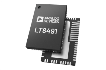
ADI Announces 80V Buck-Boost I2C Battery Charge Controller
ADI has launched the LT8491 buck-boost battery charging controller that supports MPPT temperature compensation and I2C interface functionality for telemetry and control applications. It operates regardless of whether the input voltage is higher than, lower than, or equal to the regulated battery float charge voltage. It offers three selectable constant current constant voltage charging profiles, making it suitable for charging various types of chemical batteries.
2020.12.15by 강정규 기자
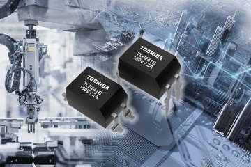
Toshiba Mass-Produces 100V DIP4 High-Current Photorelays for Industrial Equipment
Toshiba has begun sample shipments and mass production of the TLP241B high-current photocoupler. The new product is suitable for industrial equipment such as programmable logic controllers and I/O interfaces, building automation systems such as HVAC equipment and temperature control devices.
2021.02.06by 강정규 기자
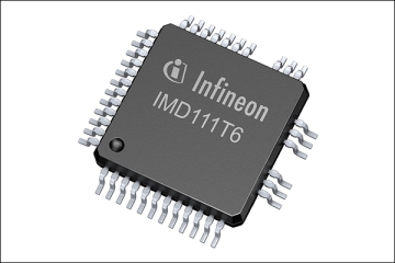
Infineon Unveils Smart Motor Controller for Home Appliances
Infineon has launched the IMD110 smart driver smart motor controller series, which integrates the iMOTION motion control engine 2.0 three-phase gate driver. The series, based on Infineon's proprietary SOI technology, is capable of driving various MOSFETs and IGBTs used in variable-speed drives.
2021.02.24by 명세환 기자

Intel Unveils Next-Generation 'Core Ultra Series 3' and vPro Platform for Enterprise PCs
Intel has officially unveiled the "Intel Core Ultra Series 3" for next-generation enterprise PCs and the latest vPro platform, addressing a wide range of demands from enterprise notebooks to high-performance workstations.
2026.03.26by 배종인 기자

ROHM Launches ESD Protection Diode Compatible with High-Speed Interfaces of 10Gbps or Higher
Semiconductor specialist ROHM has developed the 'RESDxVx series' of ESD (electrostatic discharge) protection diodes capable of responding to next-generation high-speed data communication environments exceeding 10Gbps, simultaneously enhancing both signal quality maintenance required in high-speed interfaces and IC protection performance.
2026.03.26by 배종인 기자











